
By M. Andy Kass, Denys Grombacher, Jesper Pedersen, Pradip Kumar Maurya and Anders Vest Christiansen
HydroGeophysics Group, Department of Geoscience, Aarhus University, 8000 Aarhus C, Denmark
Published 09/30/2021
Introduction
The top few meters of Earth’s surface represent an incredibly complex natural system, with interactions between the atmosphere and hydrosphere, human activity, chemistry, geology, and biology providing a dizzying array of exchanges and processes, further complicated in a changing climate. With humanity deeply reliant on this narrow strip of earth, the need for understanding, monitoring, and predicting relationships is clear. Geophysical techniques provide a window into this critical zone, yielding a powerful tool for understanding Earth’s systems.
Electromagnetic techniques are a valuable tool in a suite of available methods, allowing investigations of the subsurface in both static and time-lapse applications. Specifically, transient electromagnetics (TEM) have been a reliable method of geophysical surveying for decades. Originally a ground-based method utilizing large loops of wire in a static configuration, adaption of the technology to airborne platforms grew this technique from a point-wise measurement to a full mapping tool. However, the resolution from an airborne system coupled with its expense left a gap in mapping applications which has only relatively recently been filled with a new class of TEM instruments: those that can be towed.
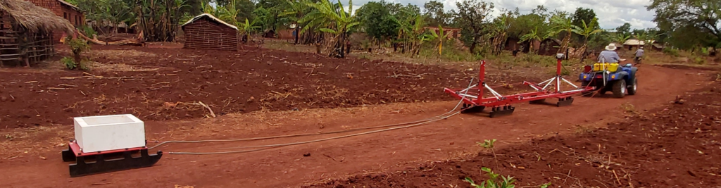
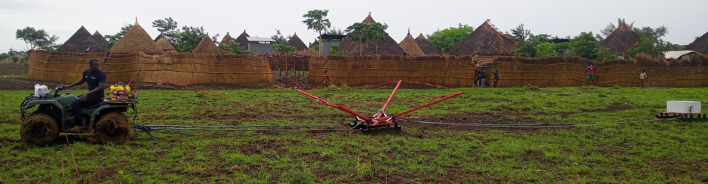
One such system, the tTEM or Towed Transient ElectroMagnetic instrument (Figure 1), has now been used all over the world to answer hydrologic and geologic questions, from the tropics to the Arctic, on land and over water. Relatively easy to ship and deploy, the tTEM has enjoyed success in mapping aquifer-hosting geology, contamination pathways, saline infiltration, permafrost conditions, and more. Here we give a brief overview of the system and its three major configurations: the land-based tTEM, the water-borne FloaTEM, and the snow-based SnowTEM. An example of each is shown to illustrate the diversity of the instrument in a wide variety of applicationsadaptability and insight towed TEM methods can provide for addressing a diverse range of problems communities face due to knowledge gaps in the subsurface and changing climatic conditions.
Towed electromagnetic arrays
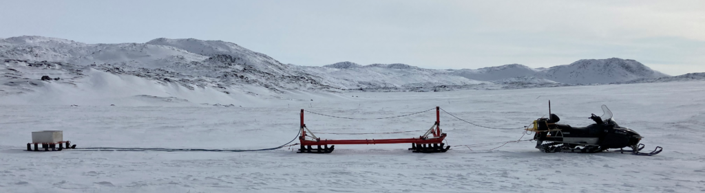
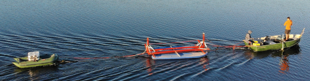
The tTEM system is available in three main configurations: land-based (tTEM), water-borne (FloaTEM), and snow-based (SnowTEM). Each of these is built on the same fundamental framework, with adaptations to each environment. Two transmitter loop configurations are presently used: a 2 m x 4 m loop and a 3 m x 3 m loop, both providing advantages in particular scenarios. While a 3×3 system is easier to deploy and lighter, the 2×4 has superior stability, for example, in a floaTEM setting. Figure 1 shows examples of (a) 2×4, (b) 3×3, (c) SnowTEM, and (d) FloaTEM systems.
Each system is simple to break down and easy to ship. A system can be disassembled or reassembled in a few hours and packed into a standard shipping pallet, with four of the long beams wrapped and shipped as a second package.
tTEM
The tTEM instrument was designed from the start as a towed system, borrowing from experience in both ground-based and airborne TEM platforms. Ultimately, the tTEM needed to be portable, easily shippable, and yet robust enough to handle rough terrain and a variety of geological environments. In general, the system consists of an electronics package mounted on the towing vehicle, a transmitter sled, and an offset receiver sled. The configuration, transmitter/receiver characteristics, and electronics are tailored to the specific type of survey, for example ATV-towed versus boat-towed.
The instrument has a dual-moment transmitter output, alternating between a high and low moment to allow for high near-surface resolution without sacrificing depth of investigation. Included in the electronics is a GPS receiver and logging computer.
The transmitter frame sits 3.5 m behind the towing vehicle, which is sufficient for a negligible influence from an ATV or small boat—larger boats or vehicles require longer lead-in cables. Transmitter configurations vary in geometry (Figure 1a and b), most commonly with an area of 8 to 9 m2 with multi-turn coils also available. The receiver is set in an offset configuration, usually 7.5 m behind the transmitter, and has an effective area of 20 m2. Standard depths of investigation for ground-based surveys can be up to 80 m or deeper depending on the geological context. Full details of the system are available in Auken and others, 2019.
SnowTEM
The SnowTEM uses a modification of the 4×2 tTEM system, adapted for driving behind a snow machine (Figure 1c). Various configurations for different applications have been deployed in Greenland, including a system with multiple receivers.
The initial Arctic SnowTEM configuration was developed to find a large (~100kg) titanium object in the ice sheet: a part lost during the failure of an airplane engine while in flight. To detect such a small but highly conductive object buried in the snow, the standard 4×2 tTEM system was modified to have a multi-turn 4×4 m transmitter for maximum moment, and two RC20 receivers towed behind in parallel. Additionally, the skis were widened by 200%. This system was successful in locating the lost part, and much was learned about Arctic deployment.
Today, the SnowTEM system requires little modification from a 4×2 tTEM system. Only in the wettest and heaviest of snows does additional surface area on the skis help—for most snow conditions conducive to a snow machine the standard skis operate adequately. Cold temperatures are also not troublesome; a stable transmitter temperature can be maintained to at least -20 °C ambient (the lowest temperature tested), and no parts become overly brittle.
FloaTEM
Like the SnowTEM system, the FloaTEM has minimal modifications to the configuration of the 4×2 tTEM. A significant addition is that of a depth sounder for accurate water depth measurements. The transmitter is mounted to two inflatable paddleboards with added structural support, with the receiver mounted in an inflatable rubber boat (Figure 1d). Depths of investigations in shallow lakes have reached over 80 meters, while in fjords and near-shore saltwater settings are more limited: around 30 meters. The DOI depends on the conductance (product of conductivity and thickness) of the water column.
Case studies
We present three case studies to demonstrate the flexibility of this towed system in a variety of environments: a water mapping and availability project in Tanzania, a permafrost and soil mapping survey from Greenland, and a combined tTEM/FloaTEM survey at Sunds Lake in Denmark.
Tanzania
The Tanzania campaign aimed to highlight the value that the tTEM’s rapid mapping capabilities can bring to well-siting frameworks in regions with little-to-no a priori knowledge of local groundwater systems. The campaign was done in partnership with the Poul Due Jensen Foundation and Water Mission Tanzania, with an aim to help guide future drilling efforts in a number of refugee camps and host communities in northwestern Tanzania. The communities in these regions are largely dependent on surface water and shallow aquifers—accessed either through hand-dug or shallow hand-pump wells or at the surface via springs. In several communities deeper boreholes have been drilled and produce from regional basement aquifers, present at the base of the regolith atop the bedrock interface. Given the expensive nature of drilling in these regions, every effort must be made to ensure the likelihood of successfully intercepting a safe water source at depth.
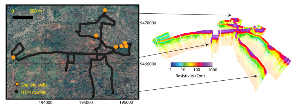
A three-week campaign was conducted in five host-communities and two refugee camps. Typical production rates were between 10-25 kms of line-data per day, often allowing a 3-4 km vicinity of the communities to be mapped sparsely within a single day by a small field crew of two people. The terrain in many cases was difficult to navigate, generally limiting coverage to non-treed areas passable by the ATV. Walking paths and dirt roads were often the best locations for data collection, but the low-friction surface proved challenging for keeping the towed system in the required straight line. The solution was to limit driving speeds to walking speed allowing one of the field crew to assist in maintaining alignment of the system. An additional learned-lesson was how difficult sourcing small-trailers (e.g., boat trailers) can be in certain regions, which led to a redesign of the transmitter frame after the campaign to allow the entire system to be fit into a single pick-up truck bed (excluding ATV).
The surveys were conducted in a regolith setting, which occurs in settings of tectonic stability where erosion rates are exceeded by weathering rates. Precipitation leeches soluble minerals from the uppermost depths, in this case an iron-oxide-rich laterite, transporting these materials further down the depth column, leading to a clay-rich layer. Beneath this layer is a weathering from where weatheringan interval where weathering decreases with depth until the bedrock interface is encountered. From a groundwater perspective, the clay-rich layer acts as an aquitard, often leading to an unconfined aquifer system near the surface (sourcing water in shallow wells/springs), as well as the presence of deeper confined aquifers often termed basement aquifers. These basement aquifers can often be highly productive and were the targeted system in the Tanzanian campaign.
Surveys reveal widespread three-layer systems in the electrical resistivity images, interpreted to be the upper laterite (resistive), clay-rich layer (conductive), and underlying weathered bedrock (resistive). The tTEM system was able to rapidly map continuity of the three-layer system, as well as layer thicknesses, to help identify attractive drilling sites near the communities.
Ilulissat, Greenland
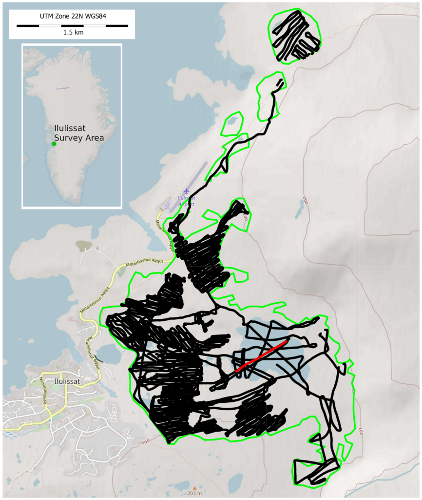
In the spring of 2021, a 4×2 tTEM was deployed to investigate groundwater and permafrost conditions around the town of Ilulissat in western Greenland at the mouth of the Ilulissat Icefjord (Figure 3, map of survey area). The potential future effects of the interactions between saline clay, groundwater, permafrost, and the lakes which hold the town’s water supply are not well understood in the context of a warming climate, and as such multiple geophysical methods were deployed over a 650 hectare area to quantify water supply vulnerability, and permafrost conditions to inform infrastructure expansion planning.
As with many arctic surveys, a strong induced polarization (IP) signal was nearly ubiquitous throughout the area—resulting from permafrost conditions and clay overburden—strongly complicating inversion and interpretation. Inversions were carried out solving for IP parameters to fully investigate the relationships between frozen active layer soils depleted in salinity containing lower salinity due to percolation of meteoric water, deeper layers with significant unfrozen water with unknown salinity, and gneissic basement rock.
Initial processing of the data yielded a surprising variety of IP phenomena, so much so that much of the dataset was erroneously culled under the assumption that the observed signals were due to coupling. However on further investigation, the data revealed themselves to be actual real IP responses, and an intense campaign of inversion and modelling was started to understand the breadth of signal types.
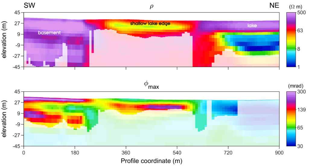
The SnowTEM was successful in mapping the catchment area. Inversion results incorporating IP phenomena (Fiandaca and others, 2018) yield insight into the distribution of clays and salinity throughout the survey as well as depth to bedrock. Figure 4 shows the inverted profile marked in Figure 3 primarily over one of the larger lakes for both resistivity and maximum phase angle, a modified Cole-Cole parameter related to chargeability. On the east side, the 18 m deep freshwater lake is clearly imaged with high resistivity and low chargeability, with a thawed, conductive area beneath. The central region covers the shallow portion of the lake, likely frozen to the base, underlain by highly-chargeable clays. Further west the lake is of negligible depth and the sediments thins to a surficial layer of silt or clay overlaying bedrock.
Sunds, Denmark
The city of Sunds, Denmark largely surrounds the 127-hectare, shallow Sunds Lake. The water table in the region has risen substantially in recent years; flooded cellars are now commonplace in winter months. Beyond the incidence of property damage, there is a risk that these fluctuations in the water table can potentially mobilize point-source pollutants (such as landfills) from the near-surface which would otherwise be largely hydrologically inactive. The issue is expected to increase in severity under a warming climate.
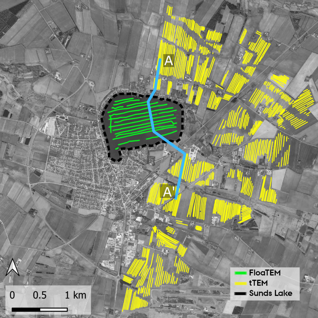
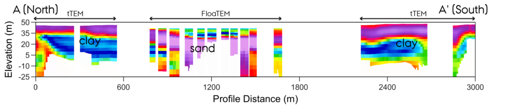
A joint tTEM and FloaTEM campaign mapped approximately 1000 hectares in and around Sunds Lake. Of principal interest was addressing a disparity between the inferred geological environment—largely sand, supported by shallow borehole surveys—and the fluctuating water table which implied the existence of a more complex system containing perhaps perched aquifers and preferential flow pathways. Any groundwater model would be incomplete without hydrologic information from beneath the lake; therefore both tTEM and FloaTEM were deployed (Figure 5).
A major benefit of the FloaTEM system is its compatibility with tTEM data. The systems operate on the same principles in nearly identical ways using the same software suite, significantly reducing the complexity of combining otherwise disparate datasets for interpretation.
The addition of the FloaTEM data to the surrounding tTEM surveys had significant implications on the hydrological interpretation and subsequent model. Without the FloaTEM data, the clay layer imaged on the flanks of the lake could easily be interpreted to be continuous beneath (Figure 6). However, the lake is underlain by sand, providing a series of hydrological pathways that could have been otherwise overlooked. The presence of Tertiary clay layers outside the lake was missed by the shallow boreholes in the region, and the spatial distribution of these is crucial not only for the groundwater models but also the potential placement of remediation measures.
Future outlook
As the tTEM systems continue to develop, we look to grow the potential applications even further. Mapping campaigns are currently planned or underway in Europe, Africa, and the U.S. to address water supply and contamination issues. A major research focus currently involves drone-mounted receivers (DroneTEM) to further increase production rates and resolution. A system designed for higher near-surface resolution (SoilTEM) has been trialed with a smaller dual-transmitter coil that includes a horizontal component. The flexibility of the instrument provides a plethora of opportunities for as yet unforeseen applications.
Conclusions
The tTEM, FloaTEM, and SnowTEM systems have wide applications to environmental and engineering studies in a variety of environments. With the abilities to be rapidly deployed and cover large areas with high resolution, these systems can provide critical information independently or to complement larger investigations. As the global climate continues to change, predicting the consequences of decreasing/increasing rainfall, population increase, land-use change, and an innumerable list of other factors on water availability and quality, permafrost conditions, and many other critical zone applications, becomes ever more difficult and important. Taken together with all available data, towed TEM methods can provide valuable insight in solving problems of environmental sustainability and protection.
References
Auken, E., Foged, N., Larsen, J.J., Lassen, K.V.T., Maurya, P.K., Dath, S.M., and Eiskjær, T.T., 2019, tTEM—A towed transient electromagnetic system for detailed 3D imaging of the top 70 m of the subsurface: Geophysics, v. 84, no. 1, p. E13-E22.
Fiandaca, G., Madsen, L.M., and Maurya, P.K., 2018, Re-parameterizations of the Cole-Cole model for improved spectral inversion of induced polarization data: Near Surface Geophysics, v. 16, p. 385-399.
Bios
Andy Kass:
M. Andy Kass completed his Bachelors in Geophysical Engineering and PhD in Geophysics from the Colorado School of Mines. He has sinced worked as a research geophysicist with the US Geological Survey and as a Postdoc and geophysicist with the HydroGeophysics Group at Aarhus University. His research interests include electromagnetics, potential fields, and nuclear magnetic resonance, especially applied to polar regions.
Denys Grombacher:
Denys Grombacher received a Bachelors in Astrophysics from the University of Alberta, and a PhD in Geophysics from Stanford University. His research focuses on development of nuclear magnetic resonance and transient electromagnetic technologies for groundwater investigations. He also likes fishing and hockey.
Jesper Pedersen:
Geophysicist at Aarhus University, Department of Earth Sciences
Pradip Maurya:
Pradip Kumar Maurya is a Geophysicist at Hydro Geophysics group at Aarhus university. He received his Ph.D. degree in 2017 within direct current resistivity and induced polarization (DCIP) method. Apart from DCIP method, his research also focuses in field of Airborne and ground-based electromagnetic methods for near surface applications. He has a vast experience in data processing and inversion of electrical and electromagnetic data. He has also a strong interest in development of geophysical instruments and currently involved in the development of tTEM instrument.
Anders Vest:
Anders Vest Christiansen did his PhD at Aarhus University where he is also working today as Professor and leading the HydroGeophysics Group. The research focus spans the entire range from development of instruments over processing and inversion of geophysical data to integration into hydrologically based decision models.
