
Abstract
Standard geophysical exploration methods can be applied to mine site problems including defining or extending ore reserves and assisting mine operations. Examples are all from Zimbabwe or Namibia and include electromagnetic, radiometric and seismic methods. Creative thinking to suit the local situation is sometimes necessary. Ore types include gold, copper and chromite.
Introduction
This article discusses some student projects completed while I was a Senior Lecturer in charge of an M.Sc. course in Exploration Geophysics at the University of Rhodesia (now Zimbabwe), and subsequent work I did as Chief Geophysicist of Tsumeb Corporation (TCL – part of Newmont Mining) in Namibia, in the 1970s and 80s. The university work was done during the period of international sanctions (1965-1980) on the then Rhodesia, leaving us with access to limited (mostly donated) geophysical equipment, and anything we could build ourselves, on a very slim budget. So these projects were done on a “worn shoe-string”. The TCL work was done with the resources of a medium-sized mining company with technical backup from a technically advanced major company (Newmont), so the resources were considerably more sophisticated, but we sometimes addressed immediate mining problems with remarkably simple means. Both university and company roles presented a wide range of technical challenges. These are just a few.
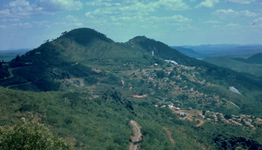
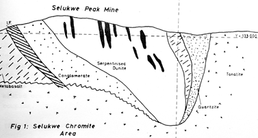
Selukwe Peak Chromite Mine, Zimbabwe (in-mine Reflection Seismology)
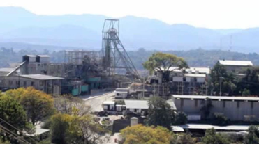
This work has been described by Polome (1978) and Green (1979). Selukwe Peak (Figures 1 & 2) mined podiform chromite hosted in serpentinised dunite.
Traditionally, new pods have been found by intensive drilling. The operators (Union Carbide) were keen to find a more economical method and had tried commercial reflection seismology (using Prakla Seismos) from the surface. This was defeated by the low frequencies and therefore resolution achievable from the surface, because pods showed up (at best) as diffraction points. We tried in-mine surveying using magnetic, gravity and resistivity surveying, with positive but not operationally useful results.
We developed an in-mine reflection seismic method from first principles. Most rocks in the target area had a p-wave velocity (Vp) near 5 km/s, so that refraction was not an option, but there were density (ρ) differences, so that the acoustic impedance Z (ρVp) showed a contrast and we could expect a significant reflection coefficient RC {=(Z1-Z2)/Z1+Z2)}. To get useful reflections, the wavelength of the sound waves must be less than the width of the pods, so we used the highest frequencies available to us (2-5 kHz). This gave a wavelength of 1 – 2.5 m, comfortably less than the pod dimensions.
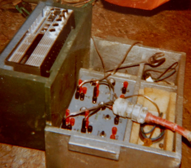
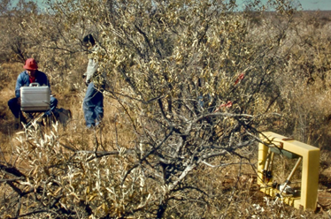
We had a tiny budget and little specialist equipment, so some hard thinking was necessary. It was imperative that the highest possible frequencies be generated, detected. and recorded, so that standard seismic equipment was useless. The source (Figure 3) was an explosive charge of 28 g of Pentolite, the fastest commercial explosive available. The source was placed down a drillhole within the mine workings, tamped with water and fired electrically. The detectors were standard Sensor Nederland SM-7/U-GT 30
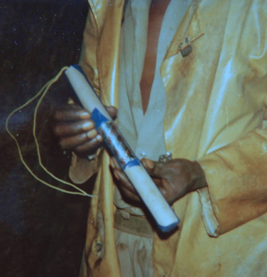
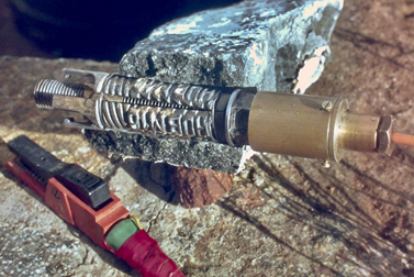
Hz P wave geophones in custom-made brass cases screwed directly to rock bolts inserted into short drill-holes (Figure 4). The geophones had a usable frequency response from 50 Hz to 5 kHz (somewhat beyond the manufacturer’s published specification). The amplifiers were home-made. The recorder was a portable stereo tape recorder, a Uher Report-S (Figure 5), and consequently we could only record two analogue traces at a time. There was some unintended EM coupling between the firing and detection circuits, so we got a zero-time mark on the record for free. Sometimes the Gods of Geophysics smile on the deserving.The tapes were played back to a memory oscilloscope and the traces photographed, to yield a workable seismic trace (Figure 6). The traces yielded seismic time from source to receiver via
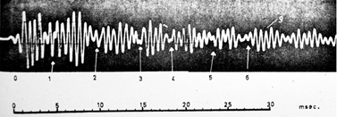
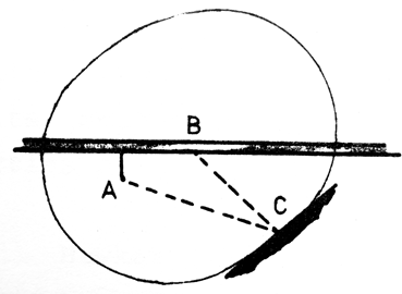
any reflector, which was easily converted to a distance using the known p-wave velocity. The reflector location was determined using the well-known property of the ellipse that distance from one focus to the other via the ellipse is a constant, so we could draw an ellipse for each detected reflection. This assumes reflecting faces are vertical, so the location can be done in plan. The reflector must be tangent to the ellipse (Figure 7).
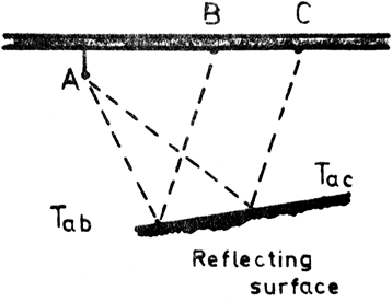
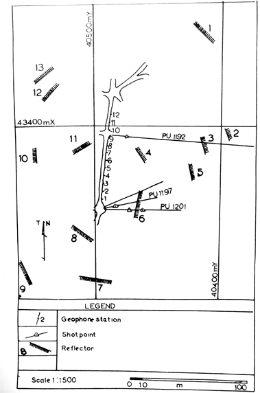
Where different ellipses (from different source-detector pairs) touched, we had a reflector location (Figure 8). The method was tedious, but cheap and effective. The results were gratifying (Figure 9). Overall, in one campaign, Green (1979) located 96 reflectors. Of these, 65 were known bodies, either chromite pods (33) or meta-dolerite dykes (32). Fourteen were new targets, with an expectation that about 50% might be chromite pods. After new drilling, 7 were identified as new chromite pods. A success! The operator attempted to develop this method using a geoMetrics Nimbus ES-1210 12-channel seismograph, sampling at 20 kHz, with encouraging results reported by Mutyorauta (1987), but subsequent follow-up was insufficient to establish a routine procedure, due to lack of funding and suitable personnel.
Arcturus Gold Mine, Zimbabwe (Radiometrics)
Arcturus Gold Mine is located 32 km E of Harare, in the Harare-Bindura-Shamva Greenstone Belt (Figure 10). It is on the site of ancient workings but has been operated in modern form since 1891 and has produced some 1.2 million oz gold. The main “ore chutes” appear to be concentrated at the intersections of two sets of felsite dykes. The operators (then LonRho) were seeking similar local orebodies on the mine property to extend the ore reserve. We were asked if we could map the dykes at surface using radiometric surveying, since they are high in Potassium. This might improve on the existing method of sampling termite mounds. A ground survey was carried out using a Chemtron hand-held gamma ray spectrometer containing a 75 mm scintillometer crystal and 30 s counting at each location. We found we could separate the results into four populations using standard geochemistry techniques which effectively mapped the local geology into Ultramafics, Epidiorite, a metasomatic zone and (hottest of all) Felsite. The dykes could be mapped effectively, and we located a new Ore Chute (Figure 11). This conclusion was checked by trenching with a back hoe and sampling. There was good correlation between radiometric
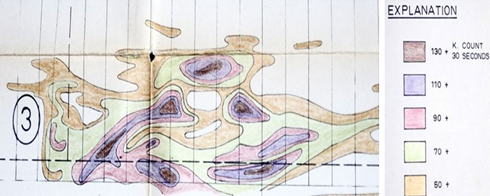
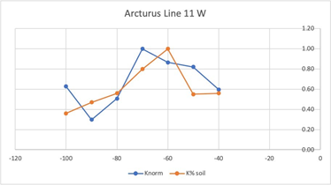
and soil chemistry with a slight downhill creep of the surface indications (Figure 12). Panning showed gold in the soil. Bingo – we had found a new ore chute, likely to expand the ore reserve.
Otjihase Deep Cu Mine, Namibia (Time Domain EM)
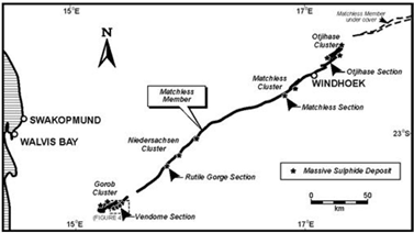
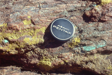
This work was described by Reid (1985). Otjihase Mine is situated some 40 km E of Windhoek. It lies within the Matchless Amphibolite Belt and is the largest known of a series of ribbon-like chalcopyrite (copper) deposits hosted in pyrite, encapsulated in a magnetite-rich quartzite (Figure 13 – Killick, 2000).The mineralised ribbon outcrops at the discovery gossan (Figure 14) and plunges at about 6° westerly for several km, reaching depths exceeding 800 m. The ribbon is intersected by several N-S trending normal faults, all down-thrown to the west. At the time, Otjihase Mine was operated by the Tsumeb Corporation, a subsidiary of Newmont Mining.
Being highly conductive, strongly magnetic, extensive and shallow-
dipping, the deposit is a VERY easy target for airborne geophysics. But the original discovery was via the surface gossan, and the first phase of mining exploited the shallower reaches of the deposit via an inclined shaft, using heavy equipment. Drilling had outlined the resource down to the “Oblique Fault”, with probable continuation beyond the down-thrown fault inferred on structural grounds. Our task was to confirm the existence of the orebody to the west of the fault and estimate its (downthrown) depth.
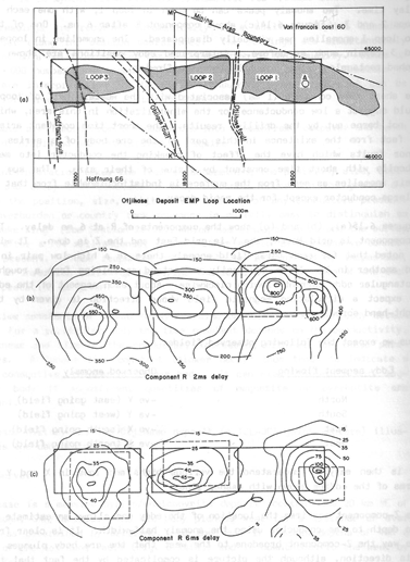
The Mark 8 version of Newmont’s in-house “EMP” time domain EM system was available. It used a fixed transmitter 400 m x 800 m single-turn loop carrying 60-80 A, approximately square, current pulses, 20 ms wide at 3 Hz. The receiver coil was successively oriented to measure N, E and Down components at a series of stations both inside and outside the transmit loop, covering 1 km square (Figure 15).
Three such transmit loop positions were employed, two over the existing known deposit and one over the inferred, downfaulted “Otjihase Deep” prospect, all within the mine licence area. All three surveys gave very definite responses, the first two as expected, given the known mineralisation, and the third as hoped, showing a similar nature to the shallower part of the deposit (Figure 16), with a depth of approximately 400m and a modelled conductivity-thickness of 220 siemens (a very good conductor).
Subsequent drilling confirmed the geophysical model, and the deposit became the “Otihase Deep” mine. We do not claim it as a greenfield discovery, because our geologists predicted its existence and location with good confidence, but the work justified and guided the subsequent drilling programme. An example of team work.
Acknowledgements
I’d like to thank Gordon Taylor for his insights, persistence and hard work, on the Arcturus Gold radiometrics project and Professor Keith Viewing of the Institute for Mining Research for his support and introductions.
References
Green, B.W., 1979. High resolution seismology in prospecting for Chromite ore. M.Sc. thesis submitted to University of Rhodesia.Killick, A.M., 2000. The Matchless Belt and associated sulphide mineral deposits, Damara Orogen, Namibia. Communs. Geol. Surv. Namibia, 12, 79-87. Mutyorauta, J. J., 1987. High resolution seismic reflection, an exploration tool within an underground environment (example from Zimbabwe). J. Afr. Earth Sci., 6, (1), 109-115.Polome, L. G. B. T., 1978. Geophysical methods of prospecting for chromite ore. M.Sc. thesis submitted to University of Rhodesia.Reid, A. B., 1985. Borehole Geophysics in The Electromagnetic Method – Field Manual for Technicians No 3, eds van Zijl, J.S.V. and Köstlin, E.O., South African Geophysical Association, Johannesburg. 302 pp. ISBN 0 620 08869 9.
Author Bio

A.B. Reid
Reid Geophysics,
Unit 3, The Coachmakers
116a Seaside, Eastbourne, BN22 7QP
United Kingdom
Honorary Visiting Research Fellow
School of Earth & Environment
University of Leeds, Leeds
United Kingdom
alan@reid-geophys.co.uk
Alan Reid is a semi-retired geophysical consultant, based in the UK. He holds a Ph.D. from the University of Alberta and an M.Phil., from the University of London. He started the Exploration Geophysics M.Sc. at the U of Zimbabwe, worked as a Mining Geophysicist for TCL (part of Newmont) in Namibia, and as a consultant with Robertson Research and GETECH in the UK. He founded Reid Geophysics in 1999.
