
Max Orman-Kollmar1, Randall Reynolds1,2, Benjamin Barrowes2, Michele Maxson1,2, Caylin Hartshorn1,2, and Fridon Shubitidze1
1Dartmouth College, Hanover, NH, USA
2U.S. Army ERDC Cold Regions Research and Engineering Laboratory, Hanover, NH, USA
Author emails:
Maximilian.A.Orman-Kollmar.TH@dartmouth.edu
Randall.W.Reynolds.TH@dartmouth.edu
Benjamin.E.Barrowes@erdc.dren.mil
Michele.L.Maxson.TH@dartmouth.edu
Caylin.A.Hartshorn.TH@dartmouth.edu
Fridon.Shubitidze@dartmouth.edu
Abstract
The process of detecting, mapping, localizing, and remediating unexploded ordnance (UXO) is both time-consuming and expensive. Cleanup costs for unexploded ordnance are significantly higher for challenging sites, such as those in wooded, rocky, wet, marshy, and rough terrain, which make up more than 50% of the 10 million acres of unexploded ordnance-contaminated sites in the United States [1]. Over the past three decades, extensive research into understanding electromagnetic induction phenomena for detecting subsurface metallic targets with high conductivity and permeability has led to the development, construction, and implementation of advanced bistatic electromagnetic induction systems. These advanced systems incorporate multiple transmitters and receivers, along with sophisticated electromagnetic induction forward, inverse, and classification models. They have provided new capabilities for UXO cleanup efforts by distinguishing potentially hazardous munitions and unexploded ordnance from non-hazardous metal debris. However, most, if not all, current commercial electromagnetic induction systems are bulky, heavy, and unsuitable for challenging terrain. In addition, the standard process involves initial dynamic anomaly detection/selection, followed by cued (static) EMI data acquisition for each detected anomaly, which result the UXO detection and classification processes expensive and time consuming. This paper presents the Ultra-Light Electromagnetic Array system (ULEMA), which the Electromagnetic Sensing Group at Dartmouth College has designed, built, and tested for the detection and classification of subsurface targets. The ULEMA system consists of three small and one large transmitter loops and four tri-axial receivers. This configuration enables the detection and classification of targets in a single pass, eliminating the need for a secondary cued data acquisition. The three smaller transmitters are strategically positioned to illuminate targets from various sides, while the one larger transmitter is designed for detecting and classifying deep targets. The instrument is compact and lighter than many systems currently used, making it suitable for deployment by hand, on unmanned ground vehicles, or unmanned aerial systems. The ULEMA data acquisition system integrates inertial measurement unit and Global Position System data to geolocate anomalies in the measured electromagnetic induction data. The system’s detection and classification capabilities are demonstrated across various modes of operation.
Introduction
UXO the lingering remnants of military training and conflicts, presents significant military and civilian challenges on a global scale. Even within the USA, roughly 10 million acres of land remain contaminated with UXO [2]. However, the magnitude of this problem is significantly exacerbated in Europe, Asia, and the Middle East due to ongoing military training, conflicts, and historical wars. The current Ukraine-Russia conflict has already led to estimations of UXO contamination spanning more than 20 million acres, an area as large as Austria [3].
Over the last three decades, the US government has made significant investments and dedicated efforts toward advancing electromagnetic induction technologies [4-12]. These advancements encompass time-domain electromagnetic induction sensing systems and physics-based data processing methods aimed at detecting, locating, and classifying subsurface metallic targets [13-17]. These sophisticated EMI devices record target responses, offering unparalleled spatial resolution and a wide spectral range that facilitates comprehensive characterization of buried objects. The effectiveness of these advanced EMI sensor technologies in discerning potentially hazardous UXO or other Munitions and Explosives of Concern (MEC) from non-hazardous metal debris has been validated through the US Department of Defense (DOD) Advanced Geophysical Classification Accreditation Program (DAGCAP) [14] and the associated international ISO/IEC 17025 standard.
Despite their capabilities in UXO detection, localization, and classification, the current commercial of the shelf (COTS) systems are focused on ruggedization and achieving classification, leading to some weighing over one hundred pounds, rendering them impractical, especially in rugged terrains such as boulder-strewn landscapes, forested areas, cliffs, and wetlands. Moreover, most systems necessitate a multi-step process involving 1) dynamic then 2) static data collection, which is more time-consuming and costlier than one-pass classification approaches.
To address these limitations, we introduce the ULEMA [15] for detecting, localizing, and classifying subsurface metallic targets. This system can be handheld [15] or mounted on remote-controlled robots [16] and unmanned aerial systems (UAS) [17]. The ULEMA captures comprehensive target responses in vector form with spatial accuracy and an extensive spectral range, enabling detailed object characterization.
Identifying subsurface targets from geophysical data involves a sequence of three stages:
1) Detection: This initial stage encompasses digital mapping of geophysical data, involving the capture of high-quality data using EMI systems. The quality of data and the responses from targets are directly affected by various factors, including the system’s capabilities, data acquisition speed, onboard processing power, as well as the size, shape, and arrangement of the transmitter-receivers.
2) Mathematical inversion: Following data acquisition, this stage utilizes comprehensive physical models to interpret EMI datasets. It estimates intrinsic target features, such as magnetic polarizations, derived from geophysical data.
3) Classification and characterization of targets: In this final phase, the extracted intrinsic parameters are utilized to categorize anomalies, distinguishing between significant targets and non-hazardous items.
Once a target response is recorded, the raw data undergoes preprocessing and inversion to extract intrinsic feature parameters. These features act as inputs for the selected classifier. The inversion process concurrently outputs object positions, orientations, and electromagnetic signatures, including the magnetic dipole polarizability tensor. These electromagnetic signatures, particularly the principal axis of the inverted magnetic dipole polarizability tensor, are then employed to differentiate detected objects, enabling the distinction between UXO and clutter.
ULEMA Hardware
The ULEMA system was constructed through a combination of customized and commercially available hardware and firmware. The system comprises a custom-designed transmission (Tx) system responsible for generating a primary electromagnetic (EM) field in the time domain, employing a square wave with a 50% duty cycle. During the on-time phase, which lasts 8.33 milliseconds, the current in the Tx system experiences an exponential rise and then maintains a constant current within the range of 10 to 20 Amperes. This current profile creates a primary magnetic field encompassing any high-conductivity metallic targets present. This magnetic field effectively penetrates inside these targets. After the on-time phase, the Tx current is swiftly interrupted, resulting in a rapid turn-off of the primary magnetic field within the targets. This fast change in the magnetic field induces eddy currents within conductive objects, leading to the generation of a slowly diminishing secondary magnetic field detected by receivers. The secondary magnetic fields give rise to an electromotive force (emf) within each of the four multi-static, multi-axis receiving (Rx) coils, which are amplified, using a custom made two-stage instrumental amplifier, and subsequently measured. These secondary magnetic field measurements are used for the purpose of detecting and classifying subsurface metallic targets.
Each ULEMA system, whether handheld, robot-mounted, or suitable for UAS, comprises two primary components. The first component is the array head, depicted in Figure 1. The second component is the electronics box, discussed below and shown in Figure 2.
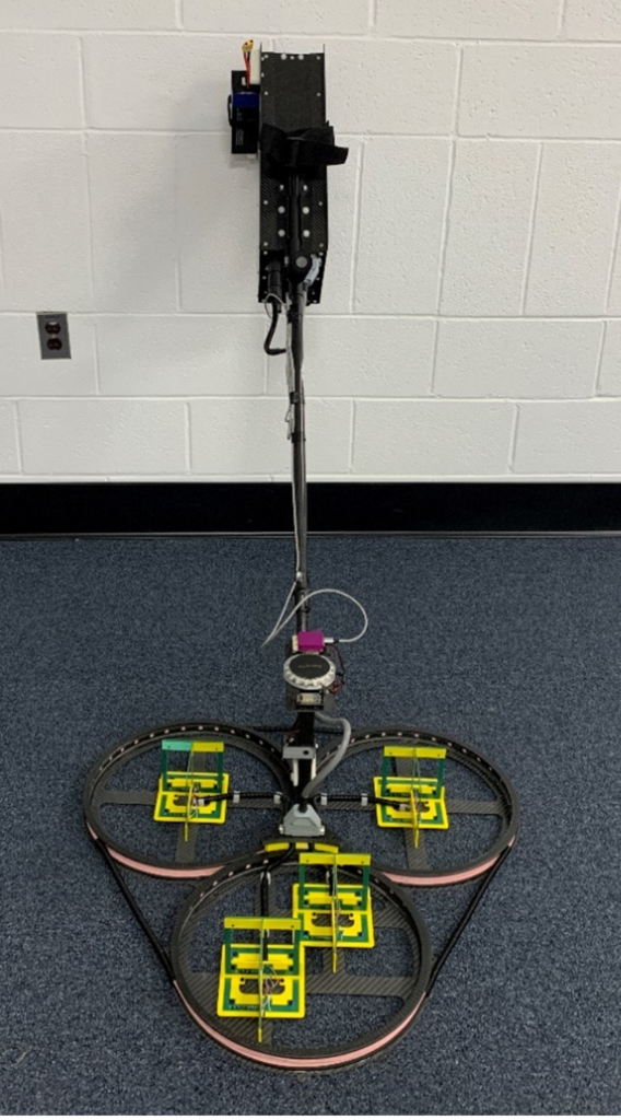
Figure 1 – View of ULEMA Array Configuration. The direction of travel is defined along the axis of symmetry of the system, with the transmitter in the front.
The array head incorporates four coplanar transmitter coils and four triaxial receiver coils positioned within the transmitters. The transmitters operate sequentially, firing every 33.32 milliseconds, resulting in seven complete datasets every second, with each complete data set made up of: four transmitters x 12 receivers x 40-time gates. Utilizing the complete data set from all four triaxial receivers and all four transmitters provide a full characterization of metallic targets exposed to primary magnetic fields from various angles. This dense data facilitates the inversion algorithm in extracting both intrinsic and extrinsic parameters from the dynamically collected data. The intrinsic parameters include the effective magnetic dipole moment, which produces size and shape. This capability enables single-pass classification.
The ULEMA array head integrates a lightweight commercial off-the-shelf Global Positioning System (GPS) module, offering real-time kinematic (RTK) positioning accuracy within 1cm at a 10 Hz data rate and off-the-shelf Inertial Measurement Unit (IMU) sensor to monitor the system’s orientation.
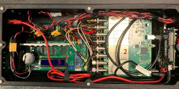
Figure 2 – ULEMA Electronics Box. The major components are (1) the brick computer running the software, (2) the Field Programmable Gate Array (FPGA) handling the incoming data and the outgoing current, (3) the transmitter board sending out the pulsed current, controlling the on and off times which allow for the decaying secondary field to be detectable, and (4) the amplifier boards, which increase the incoming data magnitude to make the responses better distinguishable, positioned directly below the FPGA.
The second primary component within the ULEMA system is the electronics box. Constructed from carbon fiber plates, this box houses several components including data acquisition (DAQ), two-stage amplifiers, transmitter boards, DC-DC power adapters, a mini-PC, and custom-made transmitter boards (depicted in Figure 2). One of the distinctive aspects of these systems is the utilization of a tailor-made Transmitter (Tx) board. This board, developed in collaboration with Dartmouth College and Subsurface Sensing Technologies and Consulting (SSTechCon), LLC, integrates Insulated Gate Bipolar Transistors (IGBTs). These components efficiently handle significant voltage and current levels, maintaining a 50% duty cycle. Alongside a microcontroller, it adeptly manages current polarity switching and synchronizes Tx currents, as illustrated in Figure 3. In addition to the Tx board’s robust capabilities, the board maintains a lightweight design and is powered by a simple 22 V battery. The board operates the transmitter loops in a sequential manner, generating currents with a 50% duty cycle of up to 20 A for each transmitter in a span of 33.33 milliseconds. This process, in turn, creates the primary magnetic field required. The entire activation cycle spans 133.33 milliseconds, resulting in data collection occurring at intervals of ~13 cm, achieving a frequency of 7.5 Hz.
The analog EMF signals that are saved from the receiver coils are conditioned, amplified, and then transmitted to the DAQ system. This DAQ system, comprised of FPGA boards operating at a speed of 10 million samples per second, digitizes and transmits these signals to an Intel NUC computer for preprocessing of the raw data.
Our team has designed tri-axial magnetic field sensors proficient in measuring the magnitude and orientation of decaying secondary magnetic fields, all within a lightweight triaxial sensor housing weighing 0.2 lbs. Each sensor consists of a ten-layer PCB employing center-tapped configurations, housing ten 10cm x 10cm coils on each layer, totaling 100 turns and an effective Rx area of 1m x 1m. A two-stage internally developed low-noise amplifier for signal conditioning and amplification has been incorporated.
Once the received data is measured, it is structured into logarithmically spaced time bins, resulting in the generation of transient responses using our in-house developed MATLAB-based DAQ software package. Characterizing these decay patterns is enabled through logarithmic binning of the waveform, condensing the original 83,300 samples per receive channel into 40 bins. Figure 3 illustrates raw and processed signals for both background and target scenarios.
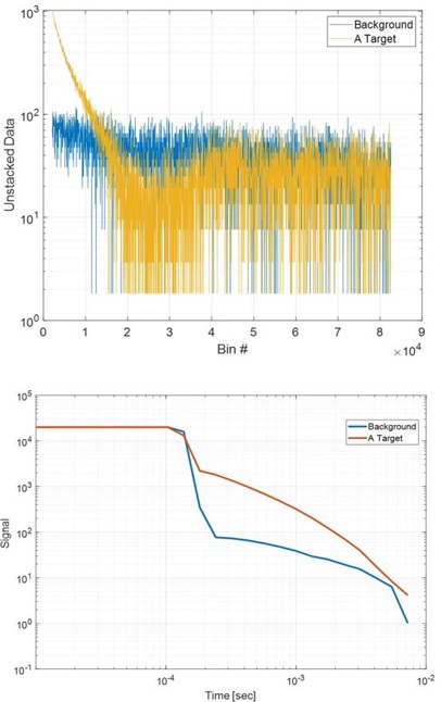
Figure 3 – Examples of raw (top) and processed/stacked (bottom) signals.
ULEMA systems
ULEMA-Handheld
The Electromagnetic Sensing Group (EMSG) lab has built and evaluated ULEMA systems in three configurations: handheld (ULEMA-H) [15], robot-based (ULEMA-R) [16], and UAS mountable (ULEMA-A) [17]. These systems utilize the same electronic components but differ slightly in Tx coil geometry, sizes, and Rx coil placements. Figure 4 illustrates the ULEMA handheld configuration, comprising three circular coils and one large loop transmitter and four tri-axial receivers. The arrangement of Rx coils is designed to yield data spaced at ~10 cm intervals along the cross-track.
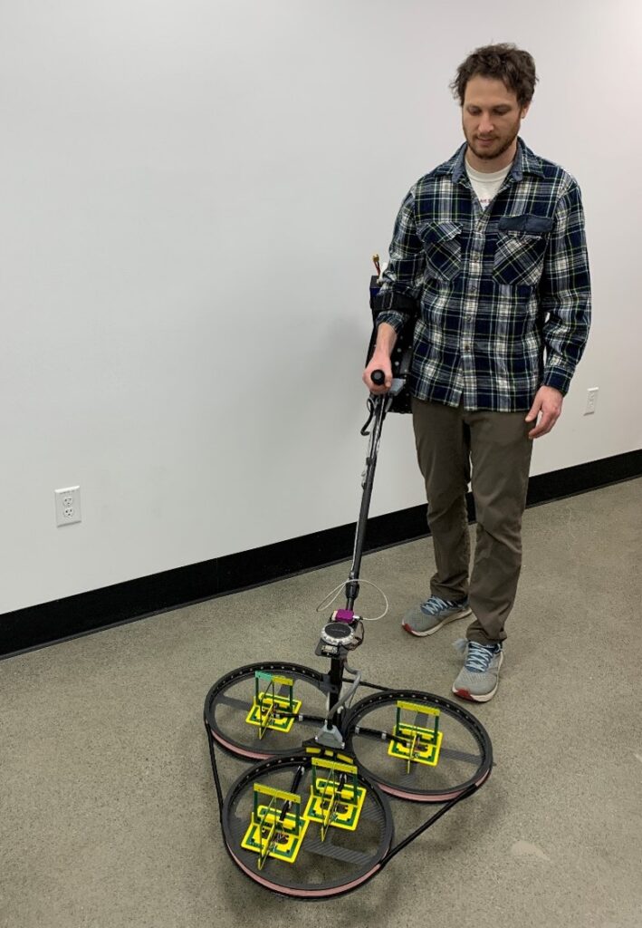
Figure 4 – Full ULEMA Handheld system
Figure 4 shows the fully assembled ULEMA-H system. A communication link can be mounted on the electronic box, which allows a user to watch the data collection in real-time on a separated screen, isolated from the data collection process. Thus, the sensor can be used in any modality, while the users can monitor it from a safe distance and see potential targets even before the data processing has begun.
ULEMA-A
A minor design adjustment is necessary for deploying ULEMA on UAS platforms. Namely, the system is suspended beneath a UAS, and all electronics are enclosed within the structure of the transmitter coils. The layout of the electronics was carefully arranged to ensure even weight distribution across the array head, promoting stable flight of the UAS, see Figure 5. Furthermore, crossbeams were incorporated at the base of the UAS to enhance stability for attaching the sensor at its designated points.
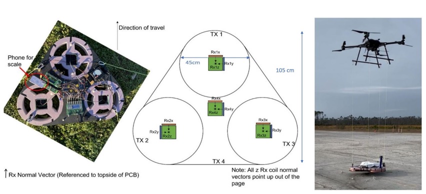
Figure 5 – ULEMA Airborne system. On the left, the general layout of the system is shown. On the right, the system suspended below a Harris HX8 UAS. Note the vertical post on the rightmost image, which holds the GPS/IMU sensor.
ULEMA-R
The robotic vehicle-based ULEMA-R system uses identical electronic components and an electronic box. However, it comprises two small (40cm by 40cm), one medium-sized (40cm by 60cm), and one large transmitter loop (wound around the two small and one medium loops). The small and medium-sized loops are engineered to illuminate targets from distinct angles, while the large Tx coil amplifies the detection, localization, and identification of deep targets. Extensive testing has been conducted at both test and blind sites, demonstrating the system’s capability to detect and classify targets up to 15x the target’s diameter. Figure 6 exhibits the ULEMA-R system along with its detection map.
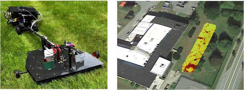
Figure 6 – Left: ULEMA-R during the data collection. Right: ULEMA-R EMI detection map overlaid on the Google map.
Results
Testing was conducted both on controlled sites and test locations. The detection depth and classification depths were both confirmed before the systems were tested on blind test sites.
Test-Stand:
Detection Depth
EMI systems, when operating in cued mode, are limited to detecting and classifying objects at offsets of approximately less than 11 times their diameter. To address this limit, the ULEMA systems were purposefully designed and constructed for the specific task of identifying deep subsurface targets using single-pass datasets. Overcoming the 11x rule was possible through updates to the custom-made amplifiers and quiet transmitter board used, which allowed for lower noise and better signal to noise ratio (SNR). Additionally, the high sample rate of 10 million samples per second allowed for more data collection and cleaning. As seen in Figure 3, the processed data shows that data decay can be seen for 5 decades, which is possible due the high sampling rate and averaging of the data in each time gate. Figure 7 shows the process of data collection and the recorded signals relative to data points for a horizontal 155mm projectile positioned beneath the ULEMA system.
To ascertain the detection depth of ULEMA systems, EMI response data from a 155mm projectile was gathered. The sensor was placed on a non-conductive raised platform, and the 155mm projectile was placed directly underneath on an adjustable surface. Starting from a 137cm offset, the system recorded static data above the target for 2-3 seconds. The target was then removed and the surface lowered. Once the surface was lowered (in 10cm increments at first, then in 5cm increments at larger offsets), the target was reinserted for another 2-3 seconds and data were recorded at the new height.
Figure 7 displays the recorded data (depicted by blue lines) for the 155mm projectile positioned at various depths. The data indicates that at shallow depths, the measured data exhibits decay following the 1/distance5 (fifth) power law, whereas for deeper targets, the signal decays according to the 1/distance6 (sixth) power law. For targets closer than 1.5x the maximum transmitter length (in this case, around 1.5m), the primary magnetic field decays as 1/distance2. Because the 155mm projectile was over 2x its maximum distance away from the Rx coils, the secondary signal emanating from it decays as 1/distance3. The product of the two decays gives 1/distance5. As the target gets further away from the transmitter, the primary magnetic field decays as 1/distance3, with the decay product becoming 1/distance6. The distance measurement is calculated from the bottom of the array to the closest point of the targets. Even at 205cm depth, which is 13x the 155mm projectile’s diameter, the signal is distinguishable from the observed noise of approximately 1×10⁻⁴ V/A. The results underscore that the signal consistently remains well above the noise level. Additionally, the signal exhibits a decay behavior between the 1/d5 and 1/d6 decay models, further corroborating the system’s effectiveness in detecting targets at varying depths. Data was also collected for a BLU-26 submunition, shown in Figure 8. The Blu-26 submunition is about 70mm in diameter, and it is clearly visible at even 85cm deep, over 12x the diameter.
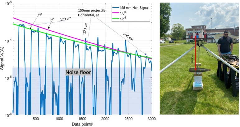
Figure 7 – ULEMA-R Detection depth for a horizontal 155 mm projectile horizontal in test-stand. The noise floor is shown for comparison (left). The test stand set-up is shown as well (right).
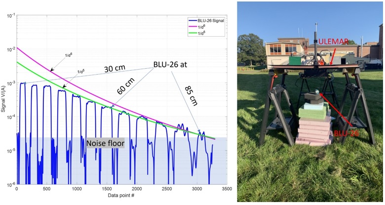
Figure 8 – ULEMAR Detection depth for BLU-26 submunition, with noise floor for comparison (left). The test stand set-up is shown as well (right).
Classification depth
The ULEMA system is designed for both deep target detection and classification. To demonstrate the systems’ limitations in classification depth, initial studies were conducted in a laboratory setting using a small industry-standard object (ISO) measuring 4 inches in length and 1.3 inches in diameter. The analysis covered both vertical and horizontal orientations at various depths.
Figure 9 shows inverted polarizabilities corresponding to different depths, with the right side illustrating the inverted depth relative to the target’s diameter. These findings indicate that the ULEMA systems adeptly determine the positions of targets up to depths 20x their diameter, while successfully extracting effective polarizabilities.
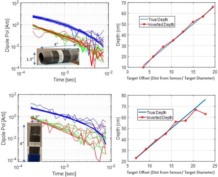
Figure 9 – ULEMA-R classification depth for a small horizontal (top raw) and vertical (bottom raw) ISO. The left column: inverted effective polarizabilities, blue, green, and red lines are primary, secondary, and tertiary effective polarizabilities, respectively. The right column: the inverted depth versus ratio true depth to target diameter.
To illustrate the performance of ULEMA systems in detecting and classifying deep subsurface targets under-real field conditions, Figure 10 displays the EMI signals detected above a buried, horizontal 155mm projectile. These detection signals were measured with the single-pass ULEMA-R systems in dynamic mode. Subsequently, advanced forward and inverse EMI models, such as combined orthonormalized volume magnetic sources and a differential algorithm, were employed to process the measured signals and extract the target’s intrinsic and extrinsic parameters for each single-pass data set. The inverted depth, measured from the array center to the center of the 155mm projectile, is 168cm and consistent with the actual burial depth of the target. Additionally, the extracted polarizabilities align with those found in the library, shown in Figure 10. These results demonstrate that the single-pass ULEMA system is capable of practical classification in field operating conditions.
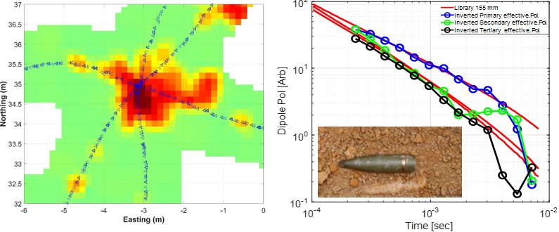
Figure 10 – ULEMA-R local detection map. Blue triangles indicate the path along which the sensor was moved over the area (left) and comparisons between extracted effective polarizabilities for library and buried 155 mm projectiles (right)
Tyndall Air Force Base
For ULEMA Airborne (ULEMA-A), data collection and testing were performed at Tyndall Air Force Base (Figure 11). Various UXO surrogates were placed inside 1.5m deep craters on the surface of the runway. Targets used mimicked 155mm and 105mm projectiles, as well as rockets and smaller munitions. Several data collection runs were performed. One run had GPS coordinates of the targets in the UAS mission planning software for the sensor to collect dynamic data while flying directly over the four targets at 1m above ground level. The other data collection runs had the UAS traverse to a GPS coordinate, with the operator manually lowering the system over each target for 20 seconds of static data collection.
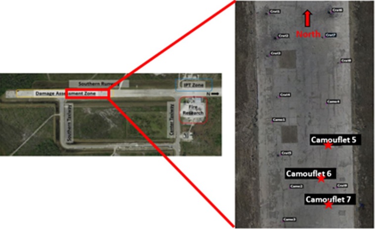
Figure 11 – Tyndall Air Force Base test site
Figure 12, shows a detection heatmap of the dynamic data collection run. All four targets are clearly visible along the flight path. The dynamic data were processed and inverted, which extracted the polarizabilities of each target. The extracted polarizabilities were compared to a set of library values, with the closest match reported as the best estimate as shown in Figure 13. The dynamic data were used to extract the polarizabilities demonstrating the capability for target classification with a single pass. The thick lines in Figure 13 represent the target polarizabilities from a previously collected library database, and the thinner lines represent the extracted polarizabilities. The extracted polarizabilities match well with the library values.
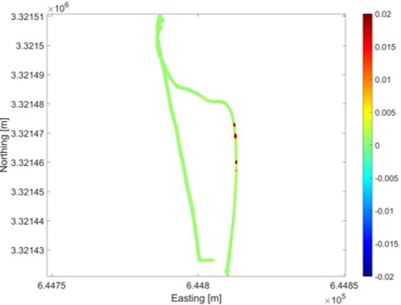
Figure 12 – Detection heatmap for Tyndall test area
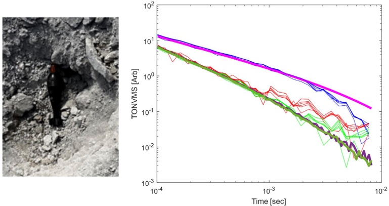
Figure 13 – 81mm projectile in crater (left). The extracted polarizabilities from the single-pass collection. The thick lines represent the library polarizabilities, while the thin lines represent the inverted polarizabilities (right).
ULEMA Studio software package
The EMI software package ULEMA-Studio, shown in Figure 14, has been designed, built, and tested to process ULEMA data sets and to meet DAGCAP requirements [14]. This software integrates functionalities such as data acquisition, sensor function testing, data pre-processing, data inversion, and automated and manual classification. Additionally, the software allows users to expand the DoD library by introducing new target entries. ULEMA-Studio facilitates the creation of site-specific synthetic data, allowing assessment of classification performance. Our DoD library encompasses a diverse collection of more than four hundred munitions items ranging from 20mm projectiles to MK84 bombs and includes similar munitions items that vary in size and shape. This library was created using EMI data obtained from laboratory and actual live UXO settings and is compatible with DAGCAP-library.
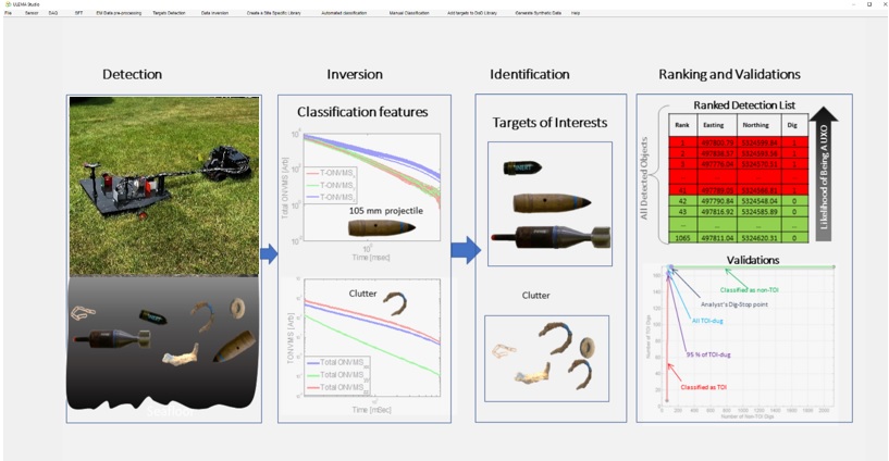
Figure 14 – ULEMA – Studio GUI
The initial phase of data preprocessing involves filtering the raw EM data to remove background noise. This process of background removal is executed for each time channel. Subsequently, the background-corrected data are gridded to generate a detection map, where users have the flexibility to select a detection threshold. Once defined, the software identifies peaks surpassing the detection threshold, designating each as a detected anomaly. The software automatically selects data points surrounding each detected anomaly, which then undergo an inversion process using advanced forward and inverse EMI models [11]. The result of this inversion process includes determining the locations and magnetic polarizability tensor elements. The coordinates resulting from inversion are converted from a local to a global coordinate system. This conversion is facilitated by the GPS and IMU data associated with each EMI data point. The inverted polarizabilities serve as classification features, which are compared against the entries in the library. This comparison between the source’s polarizabilities and those in the library yields classification confidence statistics, Figure 14, which are used to rank the sources according to likelihood of being a target of interest.
Conclusion
The ULEMA systems have been developed to address the challenges of subsurface detection and classification in difficult terrain, including densely wooded, wet, and rugged landscapes. The core components of ULEMA systems, including the Tx/Rx head and DAQ box, are designed for multi-modality applications. Compact and lightweight, the ULEMA instrument is adaptable for manual deployment, or integration with unmanned ground vehicles, and aerial systems. The data acquisition system incorporates IMU and GPS hardware to map and geolocate anomalies identified in measured EMI data. These systems produce high-quality single-pass EMI datasets, enabling characterization and precise localization of subsurface targets. The ULEMA Studio package has been specifically created for ULEMA data acquisition, pre-processing, inversion, target classification, DoD library updates, and synthetic data generation [19]. The data collection and processing workflows adhere to the DAGCAP general procedures [14]. Future endeavors will focus on DAGCAP validation of the ULEMA-Studio and ULEMA systems for application within MMRP.
Acknowledgements
This work was supported by the Office of Naval Research under grant # N00014-22-1-2396 and Airforce RADAR program.
Mr. Max Orman-Kollmar extends his gratitude to the National Science Foundation Research Traineeship, Transformative Research and Graduate Education in Sensor Science, Technology, and Innovation (DGE- 2125733) for supporting his contribution to this work.
References
[1] https://www.state.gov/reports/to-walk-the-earth-in-safety-2022/
[2] Office of the Under Secretary of Defense for Acquisition, Technology and Logistics, “Report of the Defense Science Board Task Force on Unexploded Ordnance”, December 2003
[3] Nickel, R., Polityuk, P., “Analysis: Facing minefields and cash crunch, Ukraine farmers to sow smaller crops”, 18 July 2023, Reuters
[4] Gasperikova, E., Morrison, H. F., Smith, J. T., and Becker, A., 2006, “UXO Detection and Characterization using new Berkeley UXO Discriminator (BUD)”. AGU Spring Meeting Abstracts. 2006AGUSMNS31A..02G.
[5] Geometrics’ MetalMapper 2×2. https://www.geometrics.com/product/metalmapper-2×2/
[6] Nelson, H., McDonald, J., 2001, “Multisensor Towed Array Detection System for UXO Detection”. IEEE Transactions on Geoscience and Remote Sensing, v. 39, no. 6, p. 1139-1145.
[7] Fernández, J. P., Barrowes, B., Bijamov, A., Grzegorczyk, T., Lhomme, N., O’Neill, K., Shamatava, I., Shubitidze, F., 2011, “MPV-II: an enhanced vector man-portable EMI sensor for UXO identification”. Proceedings of SPIE – The International Society for Optical Engineering. 8017. 10.1117/12.884085.
[8] Billings, S., Lutes, D., Beran, L., Rowlands, W., Mitchell, S., 2018, “UltraTEM: Flexible Transmitter and Receiver Configurations for Buried Metal Detection in Challenging and Varied Conditions”. FastTIMES, v. 23, no. 5, p. 98-107.
[9] Miller, J., Schultz, G., Shubitidze, F., Keranen, J., 2014, “Dynamic UXO Classification Sensors: Advanced Digital Geophysical Mapping for Munitions Response Sites”. FastTimes, v. 19, no. 3, p. 43-53.
[10] Bell, T., Barrow, B., Miller, J., 2001, “Subsurface Discrimination Using Electromagnetic Induction Sensors”. IEEE Transactions on Geoscience and Remote Sensing, v. 39, no. 6.
[11] Shubitidze, F., Fernandez, J. P., Barrowes, B., Shamatava, I., Bijamov, A., O’Neill, K., Karkashadze, D., 2014, “The Orthonormalized Volume Magnetic Source Model for Discrimination of Unexploded Ordnance”. IEEE Transactions on Geoscience and Remote Sensing.
[12] Billings, S., 2004, “Discrimination and Classification of Buried Unexploded Ordnance Using Magnetometry”. IEEE Transactions on Geoscience and Remote Sensing, v. 42, no. 6, p. 1241-1251.
[13] Butler, D., Simms, J., Furey, J., Bennet, H., 2012, “Review of Magnetic Modeling for UXO and Applications to Small Items and Close Distances”. Journal of Environmental and Engineering Geophysics, v. 17, no. 2, p. 53-73.
[14] https://www.denix.osd.mil/mmrp/advanced-geophysical-classification-accreditation -and- other-tools/
[15] Shubitidze, F., Saparishvili, G., Barrowes, B., Shubitidze, T., and Prishvin, M., 2021, “ULEMA: Ultra-Light ElectroMagnetic Array system for UXO detection and classification”. Symposium on the Application of Geophysics to Engineering and Environmental Problems Proceedings: 21-21. https://doi.org/10.4133/sageep.33-012.
[16] Orman-Kollmar, M., Reynolds, R., Maxson, M., Barrowes, B., Shubitidze, F., 2023, “Robot-Mounted ULEMA for Unmanned UXO detection and classification”. Symposium on the Application of Geophysics to Engineering and Environmental Problems Proceedings.
[17] Shubitidze, F., Reynolds, R., Maxson, M., Lozano, D., Orman-Kollmar, M., Quinn, B., Barrowes, B., 2021, “UAS Mounted EMI Sensor for UXO Detection and Classification”. Symposium on the Application of Geophysics to Engineering and Environmental Problems Proceedings.
[18] Maxon, M., Orman-Kollmar, M., Reynolds, R., Lozano, D., Quinn, B., Prishvin, M., Barrowes, B., Shubitidze, F., 2023, “A New Geophysical Sensor: Ultra-Lightweight Electromagnetic Array”. NATO SET-311 10th Military Sensing Symposium.
[19] Shubitidze, F., Barrowes, B., Schultz, G., Miller, J., Shamatava, I., “Generating Underwater Synthetic EMI Data Using Physically Complete EMI Models”. Symposium on the Application of Geophysics to Engineering and Environment Problems Proceedings.
Author Bios

Max Orman-Kollmar was born in New York City and received his double-majored in Engineering Physics with a concentration in Physics as well as in Middle Eastern Studies with a focus on Arabic language and literature from Dartmouth College in 2020. He subsequently received his BE in Mechanical Engineering from the Thayer School of Engineering in 2021, as well as his Engineer in Training license the following summer. He is currently pursuing his PhD at Dartmouth College in control theory and electromagnetics, working on autonomous electromagnetic sensor design and integration.

Randall Reynolds was born in New Haven, CT. He received a BS in Mechanical Engineering from the University of Vermont in 2014. Afterwards, Randall served as a Building Controls Engineer at the University of Vermont for 1 year and then as a Research/Mechanical Engineer at White River Technologies for the next 5 years. Currently, Randall works as an Electronics engineer at the Cold Research and Engineering Laboratory (CRREL). He has 8+ years of experience working with electromagnetic sensors including data collection, data processing, data quality control and sensor development. He has worked with Magnetometers, Time Domain Electromagnetic Induction (EMI) and Frequency Domain EMI for Unexploded Ordinance (UXO) detection, utility mapping and other remote sensing applications.

Ben Barrowes received the Ph.D. degree in 2004 from the Massachusetts Institute of Technology, Cambridge, MA. He was named top high school math student in the state of Utah (1991), was awarded an NSF graduate fellowship (1999), was a Director’s funded Postdoc at Los Alamos National Laboratory (2004) and was named Innovator of the Year for the Army Corps of Engineers (2019). Currently, he is a physicist with the US Army ERDC Cold Regions Research and Engineering Laboratory and is the author or coauthor of over two hundred scientific publications. His research interests center on electromagnetic wave theory and modeling with applications including electromagnetic induction methods for detecting and classifying subsurface objects, novel fusion energy generation, and the intersection between modern technology and political science.

Ms. Maxson has undergraduate degrees in both mathematics and physics and a masters in geoscience. She started her career in private industry working as a LiDAR data analyst. She moved to the federal sector working with the United States Army Corps of Engineers focused on near surface geophysics and the problem of remediating unexploded ordinance. She is now working toward her PhD at Dartmouth College in Electrical Engineering focusing on advanced geophysical classification systems and their associated algorithms. Ms. Maxson’s research is the design and implementation of algorithms for both time and frequency domain electromagnetic induction sensors. She is the recipient of multiple awards for her research including the 2018 ERDC Program Development Award for her work with the Unconventional Countermeasures Program and the 2023 NATO SET Panel Young Scientist Award for her work with the Ultra-Light Electromagnetic Array (ULEMA).

Caylin Hartshorn served on active duty in the United States Marine Corps as a digital wideband equipment operator from 2009 to 2013. After leaving all military service he attended the University of Missouri – Kansas City (UMKC) where he received his B.S. in electrical and computer engineering (ECE). Caylin began his civilian federal service with the U.S. Army Corps of Engineers in 2018 when he joined Rock Island District. He worked at Rock Island until 2020, when he accepted his current position as an electrical engineer at the U.S. Cold Regions Research and Engineering Laboratory (CRREL) located in Hanover, NH. At CRREL, Caylin is part of an electromagnetic sensing research group that specializes in subsurface classification and detection, such as UXOs, IEDs, permafrost, voids, and civil works utility infrastructure. He currently attends Dartmouth College, Thayer School of Engineering, where he is pursuing his PhD in electrical engineering.

Fridon Shubitidze (A’98–M’04) earned a Diploma in radio physics (M.S.) from the Sukhumi branch of Tbilisi State University (TSU), Sukhumi, Republic of Georgia, in 1994. He obtained a Cand.Sci. (Ph.D.) degree in radio physics with a specialization in applied electromagnetics from TSU in 1997.
Beginning in 1994, Shubitidze served as a Member of the Research Staff at the Laboratory of Applied Electrodynamics within the Department of Physics, TSU. Simultaneously, he held a position as a Senior Teacher at the Department of Physics and Mathematics, Sukhumi branch of TSU, eventually becoming an Associate Professor in 1998. Between 1998 and 1999, he undertook a Postdoctoral Fellowship at the National Technical University of Athens, Greece, where he conducted research involving computer simulation of electrostatic discharge, electromagnetic compatibility’s electrodynamic aspects, numerical modeling of conformal antennas, electromagnetic wave scattering, field visualization, object identification through scattered field analysis, wave propagation studies through anisotropic, plasma, and chiral media, and innovative numerical methodologies.
In the period from June to August 2005, he held the role of a Visiting Scientist at the Department of Earth and Ocean Science, University of British Columbia, Vancouver, BC, Canada. Presently, Shubitidze serves as a Research Professor at the Thayer School of Engineering, Dartmouth College, Hanover, N.H., and a senior research physicist, at White River Technologies. His primary research interests lie in the development of electromagnetic sensing technologies, numerical modeling concerning both forward and inverse electromagnetic scattering problems, the application of magnetic nanoparticle hyperthermia and phage lysates to reprogram tumor microenvironment for cancer treatment.
A native of the Republic of Georgia, Shubitidze was honored with the Medal of Honor by the country’s President in 2019, acknowledging “his personal contributions to the advancement of science and the creation of modern technologies.” In additions, Dr. Shubitidze and his group received the Munitions Response Project-of-the-Year Award given by the Strategic Environmental Research and Development Program in 2011 for developing and demonstrating advanced EMI models and algorithms for UXO detection and classification.
