By: Kyle Hoegh, Micah Holzbauer, Michael Vrtis, Michael Wallace, Ben Worel and Eyoab Zegeye Teshale
Published: 2021/07/10
Non-destructive evaluation (NDE) has been widely used in pavements as a rapid test tool for construction quality control and structural condition evaluation of existing pavement for the purposes such as, (i) estimation of its present sufficiency (ii) estimation of remaining service-life and (iii) decision on the choice of rehabilitation measure. The nondestructive nature and the rapidity of NDE minimize disruption to traffic, provide a better indication of the variations in the pavement, and reduce the cost of testing.
Minnesota Department of Transportation (MnDOT) has a wide range of NDE equipment, which provide its capabilities for comprehensive and complete pavement evaluations. Some of them have provided support to MnDOT districts for pavement design and construction needs. This article highlights the following MnDOT NDE equipment and its capabilities along with examples of each equipment.
- Road Doctor Survey Van
- Density Profiling System
- A1040 MIRA Device
- Ground-Coupled Ground Penetrating Radar (Sink Hole Analysis)
- MnROAD Digital Faultmeter
- Lightweight Inertial Surface Analyzer (LISA)
- Automated Laser Profile System (ALPS)
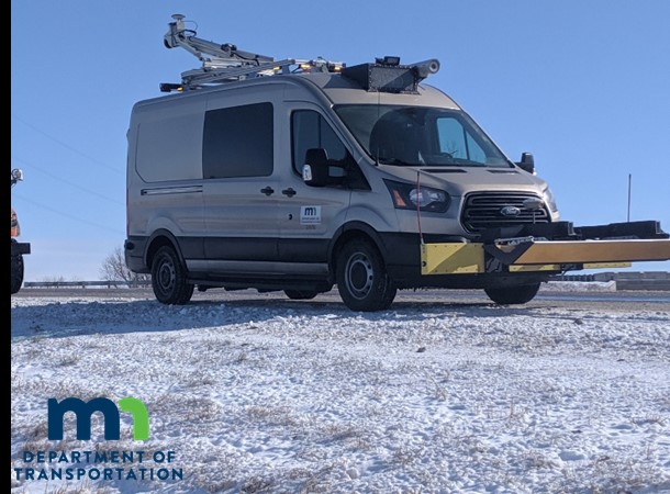
MnDOT Road Doctor Survey Van Description
Description
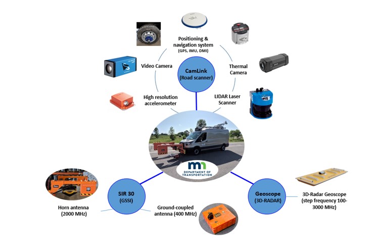
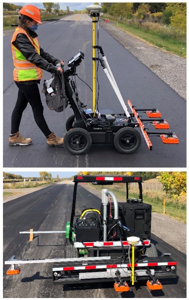
The Road Doctor Survey Van (RDSV) is an advanced non-destructive road survey technology currently being evaluated by MnDOT’s Office of Road Research & Materials. The RDSV collects continuous surface and subsurface measurements by integrating state-of-the-art hardware and advanced software to process, synchronize, and visualize large and complex data. The system comprises eight different sensors, including a LIDAR laser scanner, a high-resolution 3D-accelerometer, two high-definition video cameras, a thermal camera, and three types of ground penetrating radar (GPR) technologies: GSSI 400 MHz ground-coupled (GC), GSSI 2 GHz horn antenna, and the 3D-Radar’s step-frequency geoscope radar. All these sensors are linked to a single Global Position System (GPS) referencing system. This approach allows efficient synchronization and fusion of data from different sources and comprehensive root-cause investigation of pavement distress conditions.
Capabilities
Currently, the system is being evaluated both for project scooping and research applications. To cite a few of the applications explored:
- Pre and post-construction evaluations of roads
- Prediction of whole lane layer thicknesses
- Inspection of voids in concrete pavements
- Evaluation of roads affected by crack-heaving
- Monitoring of moisture in base aggregates
- Detection of stripping in surface layers
- Evaluation of joints in concrete roads
Examples
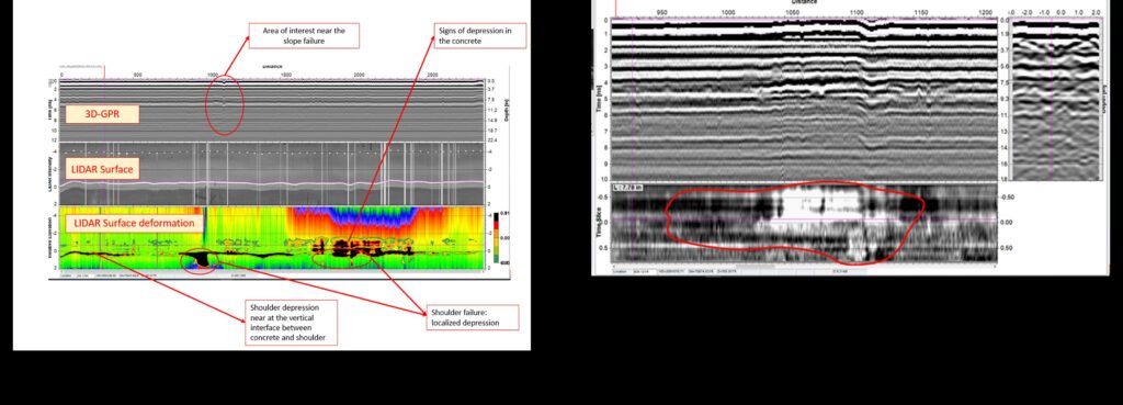
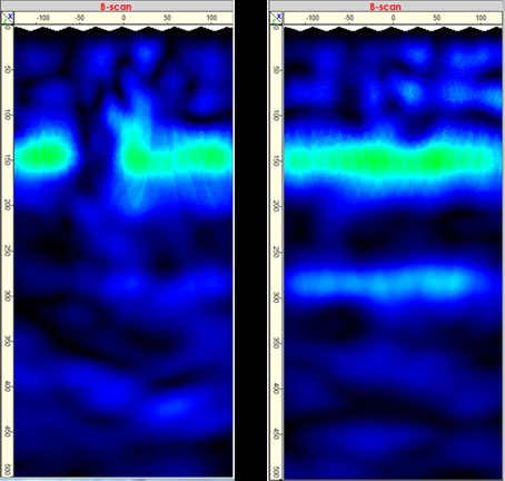
The examples shown in the figures below, from St Peter Fan Drains, demonstrate the data fusion capabilities and potentials of the RDSV. In this project, a slope failure caused the formation of voids underneath the concrete pavement and depressions (sinking) in the shoulder lanes. The 3D-GPR and LIDAR were successfully employed to locate and measure the extents of the damages both in the surface and subsurface.
MnDOT Density Profiling System
Description
Density, or percent of maximum compaction (% Gmm) of the placed asphalt pavement mat is a critical asphalt of pavement performance. However, traditionally available methods for assessment such as coring or nuclear gages are destructive and/or limited in coverage. This motivated AASHTO to conduct a SHRP 2 R06C study on technologies to enhance quality control on asphalt pavements. The promise of the density profiling system (DPS) lead to the current Transportation Pooled Fund-5(443) for Continuous Asphalt Mixture Compaction Assessment Using Density Profiling System (DPS).
Capabilities
MnDOT field trials have shown an immediate improvement in assessment coverage, with the 3 sensor DPS testing protocol resulting in data that is the equivalent of approximately 100,000 cores per mile when evaluating compaction performance [1]. However, since the density assessment is affected by dielectric properties of each specific mix, especially aggregate [2], conventional use of DPSs still require destructive coring to obtain the absolute % Gmm [3-5]. This motivated MnDOT to develop and employ a coreless calibration method using production mix samples [6]. Initial trials of the coreless method of correlating dielectric to % Gmm show promise for use if DPS to improve statistical significance of the assessment, mitigate the need for destructive field cores, and combine with other intelligent construction technology to improve construction of placed asphalt pavement density. MnDOT has also developed a gator-mounted, moveable bracket data collection method, designed to make the required labor and traffic control effects more feasible for implementation by conducting full-lane width assessment in a single pass behind the final roller compactor [1,7].
Examples: Deficiency of core assessment and potential for improved process by combining DPS with other Intelligent Construction Technologies –
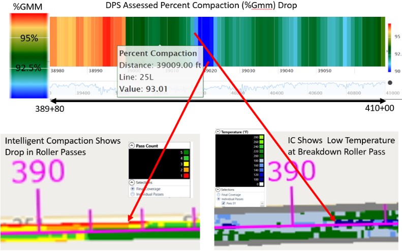
In this example, the majority of a 13 mile mill and overlay project showed very good compaction ranging from 94% to 97% compaction. However, DPS assessment showed poor compaction along an approximately 2000 ft stretch. Further analysis of the 2000 ft. stretch using intelligent compaction (IC) technology revealed the causes of the drop in compaction. Both the number of vibratory roller passes were reduced within this location, and some locations showed a drop in pavement mat temperature well below the suggested level prior to the initial vibratory roller pass. While this drop in compaction, likely to affect pavement performance, was obvious when using the continuous coverage DPS technology, the currently employed core assessment method proved incapable of detecting this large defective portion of the pavement. Despite the majority of the 2000 ft. section showing below 93% compaction and some 50 ft long sections showing compaction below 90%, the only core that landed in the stretch of pavement happened to occur at a location where both DPS and IC technology showed good compaction and construction practices. This shows both the need for improved assessment capabilities provided by DPS over the current limited random coring approach as well as the potential for combination of DPS with other intelligent construction technologies to give construction process feedback loops that lead to practices resulting in better compaction in the first place.
Published:
- Kyle Hoegh, Trevor Steiner, Eyoab Zegeye Teshale, Shongtao Dai. “Minnesota Department of Transportation Case Studies for Coreless Asphalt Pavement Compaction Assessment.” Transportation Research Record Journal Article. Volume: 2674 issue: 2, page(s): 291-301 First Published February 21, 2020: https://doi.org/10.1177/0361198120907582
- Eyoab Zegeye Teshale, Kyle Hoegh, Shongtao Dai, Richard Giessel and Curt Turgeon. “Ground Penetrating Radar (GPR) Sensitivity to Marginal Changes in Asphalt Mixture Composition” ASTM. Journal of Testing and Evaluation 48, no. 3 (2020): 2295-2310. https://doi.org/10.1520/JTE20190486
- Kyle Hoegh and Shongtao Dai. “Asphalt Pavement Compaction Assessment Using Ground Penetrating Radar-Arrays” Proceedings: Congress on Technical Advancement 2017. 118-126. 10.1061/9780784481035.011 [doi]. https://ascelibrary.org/doi/abs/10.1061/9780784481035.011
- Kyle Hoegh, Shongtao Dai, Trevor Steiner, and Lev Khazanovich. “Enhanced Model for Continuous Dielectric-Based Asphalt Compaction Evaluation.” Transportation Research Record Journal Article. Volume: 2672 issue: 26, page(s): 144-154. Article published online: September 7, 2018; Issue published: December 1, 2018. https://doi.org/10.1177%2F0361198118794068
- Kyle Hoegh, Lev Khazanovich, Shongtao Dai, and Thomas Yu, “Evaluating asphalt concrete air void variation via GPR antenna array data.” Case Studies in Nondestructive Testing and Evaluation. Elsevier. Volume 3, April 2015, Pages 27-33. https://doi.org/10.1016/j.csndt.2015.03.002
- Kyle Hoegh, Roger Roberts, Shongtao Dai, and Eyoab Zegeye Teshale. “Toward Core-Free Pavement Compaction Evaluation: An Innovative Method Relating Asphalt Permittivity to Density.” Journal Article. Geosciences 2019, 9(7), 280; MDPI. https://doi.org/10.3390/geosciences9070280
- Trevor Steiner, Kyle Hoegh, Eyoab Zegeye Teshale, Shongtao Dai. “Method for Assessment of Modeling Quality for Asphalt Dielectric Constant to Density Calibration.” Journal of Transportation Engineering, Part B: Pavements. ASCE. Vol. 146, Issue 3 (September 2020). https://doi.org/10.1061/JPEODX.0000210
A1040 MIRA Device
Description
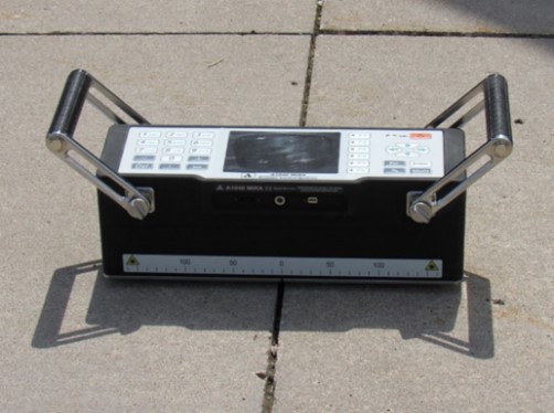
The MIRA Device is an ultrasonic tomographic device that provides imagining of the internal structure of concrete pavements. The device contains an array of 48 transducers that contact the pavement to send and receive shear wave signals. The device then rapidly converts these signals into a tomographic image. Its nondestructive and lightweight properties have proved to be beneficial in pavement research.
Capability
The device can be used for detection of voids, delamination, pavement thickness, determining depth of reinforcement, and checking for joint deployment.
A single location scan can be performed to generate a 2-dimensional image and step by step multi-point scans can be performed to generate a 3-dimensional image. To generate the 3-dimensional image external software is used. Each scan takes approximately 5-10 seconds allowing the user to efficiently test many locations.
Example
Researchers at MnDOT have utilized the capabilities of this device on a vast array of projects at MnRoad and throughout the state. It has been used in conjunction with the faultmeter to monitor joint deployment of joints that exhibit zero faulting.
The device has also been used to detect delamination, concrete thickness, and dowel bar depth as a diagnostic tool for determining causes of pavement distress and failure.
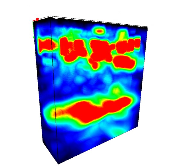
Image 3. 3-Dimensional image generated from multiple MIRA scans
Ground-Coupled Ground Penetrating Rader
(Sink Hole Analysis)
Description
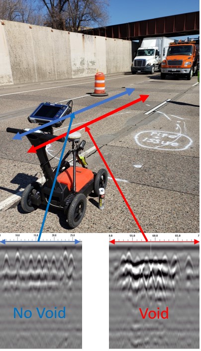
Sink holes can result in dangerous conditions on the pavement surface for the traveling public. While knowledge of the environmental conditions and chronological evaluation is often required to determine the exact mechanism of the sink hole, MnDOT often employs ground penetrating radar (GPR) after the problem has manifested in a surface depression. The goal is often to give a timely analysis of the sink hole extent (since the void below can extend laterally beyond the visible surface), and estimate the quantity of material required to fill the underlying hole.
Capabilities
MnDOT has employed both low-frequency ground-coupled GPR and step-frequency air coupled GPR. The former (GSSI UtilityScan Pro Ground Penetrating low frequency 350 MHz HyperStacking antenna (350HS)), allows for deeper penetration that can occasionally directly map the void surface extent by analysis of the increase in direct reflection. The latter (3D Radar DX 200 MHz to 300 GHz frequency range 21 channel antenna) allows for a 5 ft. coverage at 3 in. spacing between antenna pairs that gives a high resolution map that can occasionally map the extent of the surface depression and allow for calculation of the amount of grout or other material necessary to fill the underlying void. MnDOT pairs both devices with RTK GNSS (Trimble R8/TSC3) to allow for geolocated post-processing analysis to supplement the real-time investigation.
Examples
Ground coupled I-694 void delineation – Early in the morning of April 1, 2021, a void beneath mainline I-694 was observed by a night maintenance crew near a stormwater sewer pipe and the lane directly above the void was closed. The strong reflection of the interface between concrete and void allowed the ground coupled GPR to map the perimeter of the apparent void beneath the surface. The quick and effective results of the GPR investigation provided timely information for safe and effective lane closure decisions, and the void was ultimately repaired when the faulty section of pipe was removed and replaced.
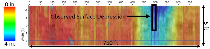
Air coupled TH-14 settlement mapping – The 3D Radar multi-channel GPR collected data at highway speed covering a 5 ft wide 750 ft. long stretch with a small pavement depression. A colormap of the settlement is given, showing 0 to 4 in. of layer depth increase leading up to the surface feature. The extent that the loss of material occurred laterally beyond surface observable feature and depth of settlement was used to help engineers estimate grout quantities required.
MnRoad Digital Faultmeter
Description
Joint faulting occurs in concrete pavements from a heavy vehicle loading presence. High levels of faulting result in a poor ride quality. To better understand the causes of faulting, it must be measured and quantified with extreme precision and accuracy.
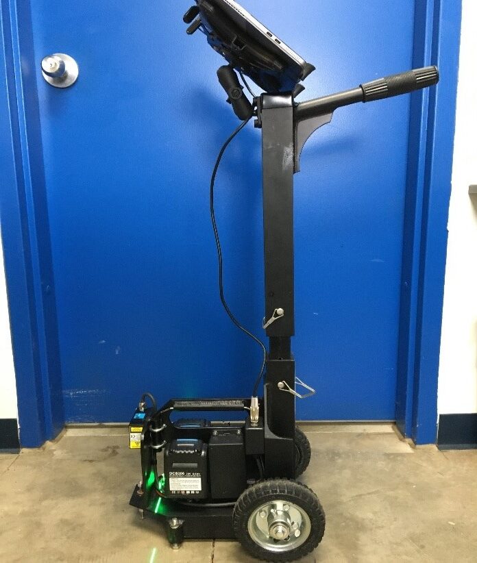
The MnRoad Digital Faultmeter is an electronic digital device that is used to measure joint faulting in concrete pavements. The device includes a high precision laser that measures the change in elevation between the two adjacent panels at the joint. The device is manually placed at each location and a single point measurement is collected. Values are collected instantly and stored on the device for further analysis.
Capability
The Digital Faultmeter allows researchers to collect faulting measurements quickly and efficiently at MnRoad several times throughout the year (Approximately 3-4 times annually). These measurements provide a better insight at the long-term pavement performance.
The device includes a high visibility line laser to provide consistency at each joint. The three-legged footprint allows the operator to quickly place the device down at each location to collect a reliable and repeatable measurement.
Example
The device is currently being used to monitor joints at MnRoad. Multiple measurements are collected on joints at varying offsets. Testing locations are painted at each joint to maintain consistency. Due to the device’s portability, researchers are also able to bring it to other sites throughout the state of Minnesota to gain insights on those projects’ performance as well. After analyzing the data, trends are observed to determine if faulting is increasing and to what severity.
Lightweight Inertial Surface Analyzer (LISA)
Description
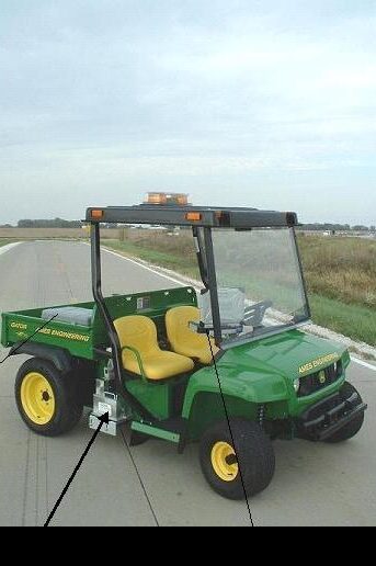
The lightweight internal surface analyzer (LISA) consists of a laser/accelerometer system mounted to a John Deere Gator Utility Vehicle. The LISA is used to measure the longitudinal pavement profile of each of MnROAD’s test sections at 10 mph. LISA collects the profile in both the inside and outside wheelpaths of a lane simultaneously. Based off the longitudinal profile collected, the rideability or roughness of the pavement is quantifies using the International Roughness Index (IRI).
Capabilities
MnROAD’s LISA has been update several times as new technology and research has improved the repeatability of profile measurements on various pavement surface texture. MnROAD’s current LISA, utilizes a Roline instead of the point lasers used on the original versions of LISA.
The raw LISA profile is exported as an .ERD file and PROVAL is used to calculate the International Roughness Index (IRI).
LISA is used to measure the surface profile of all test sections at MnROAD three times per year. The collections are seasonal, typically occurring in March, July, October of each year to capture changes before and after Minnesota’s harsh winter conditions.
Examples
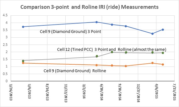
MnROAD helped demonstrate how different laser types used to determine ride do not all act the same for different types of pavement types. Over the years MnROAD has installed different types of lasers on it light weight profiler. Over the years we have progressively and simultaneously installed single point, three point, 1K ROLINE, and 3K ROLINE lasers because each improved the consistency of the ride (IRI) measurement. Point Lasers have been documented in surfaces with longitudinal texture direction (such as diamond ground pavements) to misinterpret the transverse differences in elevation as roughness. Note that the graph below shows two concrete pavements. Cell-9 has been diamond ground and cell-12 is a conventional transverse tined surface. The diamond grinding IRI measurements vary depending on the laser used. We have found the ROLINE 1K and now 3K sensors better represent the true IRI of the roadway. However, most transverse and isotropic texture configurations such as exposed aggregate, asphalt surfaces do not exhibit the anomaly associated with point lasers.
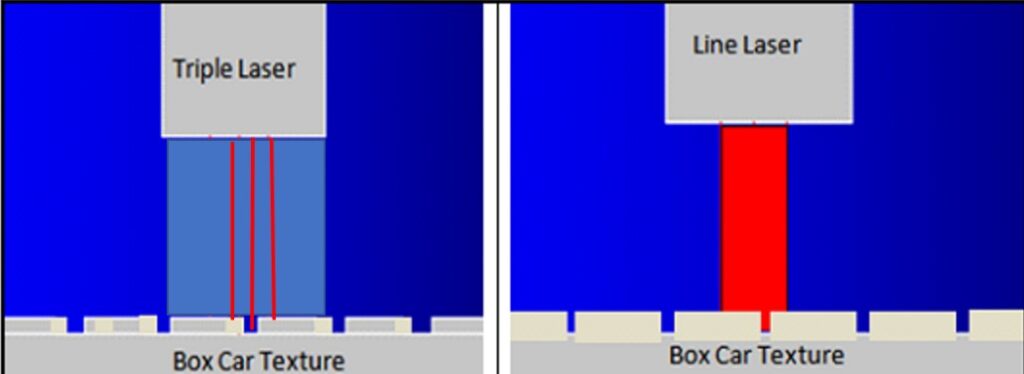
As Illustrated in Figure 2, potential skipping of Point Lasers between grooves and landing causes anomalies in Ride measurement. On the contrary, the Line Lasers provides a constant averaging and true Ride Comfort.
Automated Laser Profile System (ALPS)
Description of the equipment
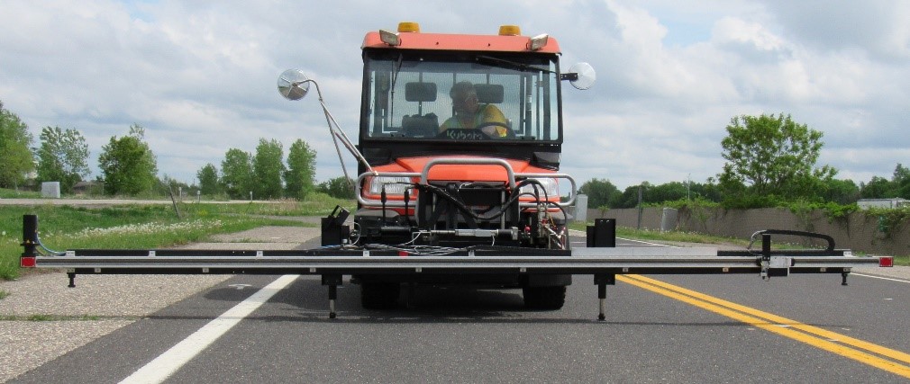
The Automated Laser Profile System (ALPS) was specially developed by MnROAD researchers to collect pavement surface profiles with a high level of accuracy. The ALPS can be used for both Portland cement concrete (panel warp/ curl) and asphalt concrete pavements (rutting). The ALPS, pictured below, consists of a 15 ft. beam that is mounted to a light utility vehicle. The beam is placed (and leveled) at the precise pavement location of interest and a laser measures the distance between the pavement surface and the beam at ¼” increments.
Capabilities
For asphalt concrete pavements at MnROAD, the ALPS measures the transvers profile by recording across the width of the pavement at fixed stations within each test section. The same locations are measured 3 times per year to capture the progression of rutting over time. An Excel-based macro program is used to process the raw ALPS data and output the maximum rut depth and location, along with the volume of water potentially stored in the rut. The ALPS is also used to measure transverse crack cupping. It is the most current device used to measure rutting at MnROAD when a high degree of accuracy is needed (non-traffic speed collections).
The ALPS has also been used for monitoring the warping and curling of Portland cement concrete pavement panels but is used more often on asphalt concrete pavements.
Examples
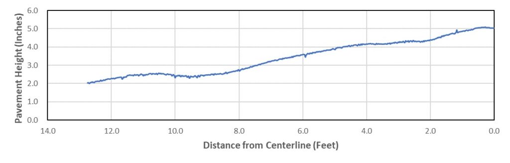
In the plot below the ALPS figure, the ALPS measured transverse profile is shown. The crown of the roadway (cross-slope) and wheelpath rutting can be seen in the plot. Show water depth / straight line calc on plot???
A more detailed description of how the ALPS was developed can be found at: http://www.mrr.dot.state.mn.us/research/pdf/2003MRRDOC005.pdf
And on the MnROAD website at: SURFACE CHARACTERISTICS OF NEW PCC PAVEMENTS (state.mn.us) LTPP InfoPave – Overview (dot.gov).