
Johannes B. Stoll
Thomas Kordes
Rolf Noellenburg
Anders Jepsen
Abstract
The Pentamag is the next generation of magnetic field sensors designed by Mobile Geophysical Technologies of Germany specifically to be carried by a custom-designed octocopter in a survey pattern close enough to the ground to detect and accurately locate small metal objects, e.g. unexploded ordnances (UXO). This system carries an array of five fluxgate magnetic sensors in a linear array. An earlier system, with a 2- fluxgate magnetometer array, has already been shown as a tool that can be useful to detect and accurately locate UXO. The Pentamag system is specifically designed with RTK location accuracy and for operation close to the ground to sense small metal objects. The magnetometer system is integrated into a specifically designed octocopter that can operate in survey mode for up to 25 minutes. Standard operational procedure is to specify a series of GPS locations to represent a regular survey, including both location and elevation above grade, based on a lidar system to guide elevation control.
Testing of the performance of this system was carried out on a military test facility in Northern Germany, on which more than 50 metal objects (amunition) were buried at known locations and depths. The size of the area is about 1 hectare. The time needed to screen this area was about 20min. The field test demonstrated that the system prototype is fully functional in an operational environment. As result the multicopter borne Pentamag system is capable for detecting and locating objects of sizes of at least 3.7cm.
Introduction
Multicopter borne geomagnetics has the potential to effectively and efficiently cover large tracts of land and wide areas for the purpose of screening and identifying areas that potentially contain unexploded ordnance (UXO). Large areas across many countries are potentially contaminated with UXO, with some ranges encompassing tens to hundreds of thousands of hectares. Ultimately, safe clearance of contaminated areas requires a standoff or an unmanned, remote detection capability due to the inherently unsafe nature of UXO. Technologies are needed which will allow for cost effective wide area scanning with near 100% coverage and near 100% detection of subsurface ordnances. But current sensor systems have very limited capabilities to discriminate clutter from UXO. As a result, nearly every anomaly must be excavated to determine if it is, in fact, an UXO.
Current technologies, either walking on ground or manned helicopter, can achieve these requirements. Two manned helicopter based systems have been developed over the past decades in the USA, the ORAGS (Oak Ridge Airborne Geophysical System) system developed by Oakridge National Lab (Doll et al. 2001; Gamey et al. 2003) and the Multisensor Towed Array Detection System (MTADS) system developed by the Naval Research Laboratory (Nelson et al. 2004). Both systems are similar in design, consisting of a boom equipped with a number of cesium vapor magnetometers mounted in the front of a manned helicopter. But these systems are not cost effective, dangerous to operate, and the associated economics make it impossible for potential clients to apply universally.
In order to be effective for small UXO detection, the sensing altitude for magnetic site investigations needs to be on the order of 1 – 2 meters above ground level (AGL). An unmanned aerial vehicle (UAV) magnetometer platform is an obvious alternative to ground magnetic measurements or manned helicopters. The motivation behind such a system is that it is safer for the operators, cheaper in initial and operational costs, and more effective in terms of site characterization. Key features of our proposed system are:
- The availability of a customized octocopter platform with autonomous flight capability, payload capacity and endurance.
- assembling of five fluxgate magnetometers on this octocopter instead of only one or two sensors, which considerably enhances the resolution and detectability of small objects.
- the low power consumption of the five sensors and ancillary systems, which is negligible compared to the power ratings of the octocopter.
4.a positioning system which encompasses RTK accuracy for accurate localization of objects.
5.a laser altimeter that controls the flight altitude enabling flight operations with a ground clearance of about 1m. This ability is a key feature for maintaining low flight altitudes above ground.
The ideal multicopter magnetometer system should allow for the effective and accurate detection of metal objects of concern. Flight operations should be done by the acquisition of regularly spaced values of the magnetic field as closely as possible to the ground. Here we demonstrate that the Pentamag owns these capabilities. We have invested much time and effort to:
- improve the in-flight sensor resolution, sensor temperature stability and the reduction of sensor weight
- design and build an octocopter optimized for the deployment of five magnetometers and maximizing the endurance for this payload
- integrate a laser altimeter to maintain a constant altitude of the UAV and sensor package above the ground level
- ensure that the total weight of the system does not exceed 10 kg. In this configuration, this system is very flexible and can be used worldwide. This UAV category requires less effort to successfully apply for a flight permission and to receive export permissions for most countries.
- The data acquisition system shall allow highly advanced positioning and synchronization of the position and magnetic data. The sample rate shall be at least 100Hz.
The detection and delineation of UXO places many highly demanding requirements on the measuring system:
The ideal system needs to demonstrate near 100% detection over all terrains with very limited false alarms. This is not a technically feasible goal even for ground based systems. Therefore, a series of thresholds and requirements will be established to demonstrate a leap ahead in the capabilities and performance over current capabilities.
Detection threshold
Accuracy
Cost rates
Production rate
Accessibility
Discrimination
define a minimum size of object, that can be clearly detected by the UAV airborne system. In this study we prove that we can locate metal objects with a caliber of 3.7cm
RTK capabilities allow for 0.1m accuracy, this is the accuracy that needs to be achievable for data reacquisition
Depending on the daily production rate, a cost rate of a few cents per square is achievable
Depending on the terrain, a daily production rate of 10 hectares is feasible. The line spacing is 2m and the data density is 5 magnetic tracks per 2m. This corresponds to 75 data points per square meter.
Get access to all scenarios encountered at sites.
to date discrimination of different types of UXO is not feasible via geomagnetic measurements.
The Pentamag System: Autonomous UAV-Mag System
The Pentamag system allows for the effective and high confidence detection of munitions of concern. Using five fluxgate sensors in a linear array, the Pentamag system acquires regularly spaced values of the magnetic field as closely as possible to the munitions of concern. But the measured and reported magnetic field typically differs from the true magnetic field due to a variety of factors, including:
- positioning error (i.e., we report a datapoint at a different point than where it is truly recorded)
- sensor related effects, specifically heading error
- magnetic interferences generated by the multicopter platform
The airborne magnetometer system requires the mounting of the magnetometer on a UAV and the integration of this payload with the UAV infrastructure.
We developed an octocopter (8 engines) specifically designed and manufactured by Aerialis GbR in Bremerhaven/Germany. Figure 1 shows the complete system, consisting of the octocopter with the GPS receiver on top of the drone and the assemblage of the five magnetometers, which are mounted on a horizontal boom slung 1.50m below the octocopter.

The following Table 1 shows the key technical specifications of the octocopter.
Table 1: Technical specifications of the octocopter
Type of UAV
Autopilot
max speed
empty weight
maximum payload
endurance
personnel
temperature, humidity
wind
distance
maximum take- off elevation
Octocopter X810 (8 electric motors), X4 coaxial configuration.
The multicopter can be operated in various modes: a) manual mode, b) GPS Position Hold, c) autonomous Navigation.Terrain Following Mode, Low Voltage Protection, Homing function & Auto Landing.
Vertical: 2-5m/s Horizontal: 15m/s
4.1kg (2 batteries 4.4kg)
6,5 kg (@ 15,0 kg MTOW)
25 min @ 3.3kg payload (Pentamag system)
1 – 2 operators
-5°C to +50°C, 0% – 90% RH (non condensing)
< 8 m/s (17,9 mph / 28,8 km/h)
data link range: ≤ 1 km (@ 2.4 GHz, visual line-of-sight)
~ 2.500 m (in standard configuration)
The endurance is an important issue in commercial applications. The endurance depends on the power consumption of the propulsion system, and the flight time is limited due to the limited energy storage capacity. In addition to the propulsion system, the drag and weight of the multicopter strongly affect the flight time. Figure 2 shows the endurance as a function of the payload derived from a synthetic multicopter model for given components (battery specifications and discharge, power consumption, motors and propellers).

FLUXGATE MAGNETOMETER
The Digital Fluxgate Magnetometer which is used for the Pentamag system is a three component, high precision, low noise vector magnetometer (Figure 3). The small-sized, lightweight vector
Dr. Jepsen has had a 45-year career in various areas of geophysical exploration for minerals, energy and environmental engineering objectives. He is founder of Exploration For Humanity, a nonprofit organization dedicated to combining drones and smart-sensor technology to locate hidden threats such as landmines and unexploded ordnance.
Dr. Jepsen has had a 45-year career in various areas of geophysical exploration for minerals, energy and environmental engineering objectives. He is founder of Exploration For Humanity, a nonprofit organization dedicated to combining drones and smart-sensor technology to locate hidden threats such as landmines and unexploded ordnance.

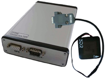
compensated magnetic field sensor is built up of self-manufactured low noise ring cores and a self-supporting Helmholtz coil system. The innovative design of the circuit boards and the ring cores reduces noise and temperature drift to a minimum and improves long term stability. The magnetometer is a stand-alone instrument.
Table 2: technical specifications of the fluxgate magnetometer system.
Field range
ADC
Resolution
Power supply
Power consumption
Sample rate
Data storage
Data format
Weight
Dimensions
Time and Position
Synchronization
Sensor construction
Sensor size
Cover
Socket
Sensor weight
Noise
Long-term stability
Orientation
Range
Orthogonality
Temperature range
± 65 μT
2x 16 bitt
10 pT
5 VDC
Minimum: 1.4 W (1 Sensor) @5VDC
1, 10, 50, 100 Hz
SD Card (4Gbyte)
ASCII, binary
ca. 220 g
16cm X 6cm X 3cm (LWH)
GPS-receiver
Internal high precision clock
self-supporting Helmholtz coil system
Height 40mm
Ø 50 mm
Ø 67 mm
105 g
< 10pT/VHz
< 10 nT per year
X, Y, Z
±65 μT
<0.02°
-20 to +75 °C
The magnetometer system uses a ublox NEO-M8N GPS receiver, which outputs the latitude, longitude, altitude and UTC time. The sample rate can be selected between 1, 5, 10, 50, and 100 Hz.
The accuracy of the position critically depends on the number of satellites available at a time. Several tests suggest that the absolute accuracy of the horizontal position derived from the GPS is in the order of 1.5 m and about 2 m for the vertical position. We implemented a GPS device that would allow to achieve RTK-accuracy (Real-Time Kinematics). An algorithm is applied for processing measurements made from satellite navigation systems to compute differential positioning using carrier phase measurements through post-processing of satellite data.
COMPENSATION OF MOTION INDUCED EFFECTS
Fluxgate magnetometers are widely used in many applications due to their low power ratings, small dimensions and their light weight. Therefore, it is the sensor of choice for deployment on multicopters. If several sensors shall be deployed at the same time on a multicopter, the total weight and the power consumption of the complete system are key. The main reason for using five sensors is to significantly increase the detectability of small metal objects in the soil. It is expected that an array of five sensors will enhance the resolution and considerably leverages the production rate.
However, fluxgate magnetometers differ significantly from other magnetometers used in geophysical exploration, e.g. optically pumped magnetometer. Fluxgate magnetometers cannot measure the absolute magnetic field. It, therefore, requires calibration using a total field magnetometer, e.g. Cs-vapor or proton magnetometer. Fluxgate magnetometers measure the magnetic field using three components. The difficulty is that even small differences in the physical design of the three components cause significant directional dependence of the total intensity of the earth’s magnetic field. These differences must be eliminated to achieve values of the Earth’s magnetic field independent on sensor motion.
This calibration procedure is different from the general method introduced by Leliak (1960) for identifying and evaluating magnetic sources associated with the magnetic airborne detector equipped aircraft. Mathematical formulas are derived aiming to compensate for the magnetic noise related to the maneuvers of the aircraft. A so called ‘clover-leaf’ test is performed and designed to demonstrate that the aircraft and system have no significant heading effects. Heading effect means that the magnetic field exhibits different values at a given location depending on the direction in which the location is overflown.
Compensation for the heading effect involves a ‘figure of merit’ (FOM) test. It usually is achieved by flying specific manoeuvres at a large distance above ground (2000-3000m) in each of the four cardinal compass directions and compensating for the differences. For unmanned multicopters the maximum flight altitude is usually limited to about 100m above ground level (AGL).
The aircraft then turns and flies over the same point again in an easterly direction, then in a southerly direction, a westerly direction and finally in a northerly direction again to check for any diurnal variation since the first overflight. With improved compensation this difference was reduced to a fraction of 1nT. Current airborne mag systems (e.g. optical pumped magnetometers) on manned aircrafts achieve a resolution of 0.2nT after compensation and better.
This process is different for fluxgate magnetometers.
There are two different principles for calibrating a fluxgate magnetometer: In a vector calibration the output of the vector magnetometer is compared with the known magnetic field vector which is applied to the instrument. In a scalar calibration only the intensity of the magnetic field is used, but not its direction.
Clearly, a vector calibration is superior to a scalar calibration if the magnetic field vector is known. If it is approximated by a model
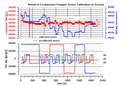
rotations are carried out. Note a few rotations are repeated. The upper panel shows the uncalibrated (blue line) and the calibrated total magnetic intensity (red line) after application of the 9 coefficients and compensating for scaling and offset-errors and non-orthogonalities. After calibration, the fluxgate sensor only slightly depends on the attitude direction. The standard deviation is 0.23nT. The peak-to-peak error is 1.5nT. The total magnetic intensity of the uncalibrated sensor exhibits much higher noise, that would not allow operation in geophysical exploration.
of the Earth’s magnetic field, a scalar calibration is probably a better choice. The calibration of fluxgate magnetometers requires to correct for scaling and offset errors of each component and transformation of the components into an orthogonal reference system to compensate for non-orthogonalities between two axes.
In case of vector calibration, the Euler angles must be known to align each component against a reference frame. However, the measurement of Euler angles requires extremely high angular accuracy (in the order of 1/100 degree). We refrain from doing so, because we are only interested in mapping the total magnetic intensity along flight lines.
Assuming a linear transfer function between the earth’s magnetic field and the magnetometer output, the rotation of the sensor around at least two magnetometer axes is sufficient to perform a scalar calibration (Auster et al., 2002). Therefore, in principle a calibration can also be performed during flight, because in this case mainly the horizontal components are rotated in the geomagnetic field. At a site, the field strength is known either from absolute magnetometer readings (optically pumped magnetometer) or from the IGRF for that site. The difference between the “true” scalar magnetic field strength and the output is then minimized by adjusting the nine coefficients representing the offset and scaling factor of each component and the non-orthogonalities.
Usually the calibration is performed on the ground without the presence of the multicopter. The magnetometer is step wise rotated about the axis of each component (X, Y, Z) by 360°. Then the total magnetic intensity is estimated via the Pythagorean theorem. An example from the military test site is shown in Figure 4.
The difference between the calibrated and uncalibrated sensor is clearly obvious. After applying the 9 coefficients there is no directional dependence of the sensor. Regardless of its attitude the fluxgate sensor picks nearly the same total magnetic intensity in any direction. The standard deviation obtained is 0.23nT.
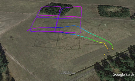
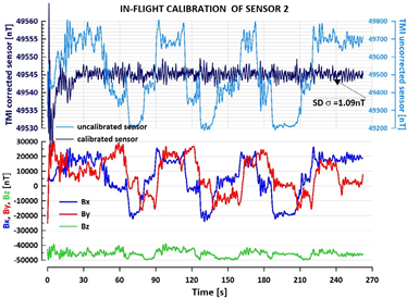
In order to include the noise and magnetic signature of the multicopter, we developed an in-flight calibration procedure. It involves executing a ‘figure-of-merit’ (FOM) flight test. The pattern is cloverleaf-shaped and flown at about 40m above ground (Figure 5). This flight pattern systematically generates rotations of the horizontal components of the fluxgate sensors, whereas the vertical component is only slightly deviated. In contrast to the calibration on the ground, which is usually performed in a magnetically quiet place, the EM interference and all magnetic components built into the octocopter superpose with the readings of the Earth’ magnetic field. The calibration also takes into account the specific magnetic signatures of the multicopter.
Figure 6 shows the results of the FOM test. It was performed on the same day of the detection test. The FOM was flown about 40m above the ground. This pattern mainly causes changes in the horizontal components but only slightly deviates the vertical component. As a result of the FOM test the directional dependence of the total magnetic intensity from direction is nearly eliminated. The standard deviation of the residual noise and the attitude dependence of the octocopter was estimated to 1.09nT. It should be noted that all data is unfiltered. The residual noise is generated by the eight electric motors of the octocopter.
Results of the Luttmersen Pentamag Test
In 2016, German federal authorities established a test field on a military training site in Luttmersen near Hanover in Northern Germany. It was chosen for a geophysical comparison test. 53 objects (ammunition, UXO) of different calibers from 2 cm to
500 pound bombs were buried in the soil at different depths and directions. The area is about 1 hectare large and comprises flat grassland. There are no bushes or other obstacles which make it a perfect site for this test (Figure 7). Since this training area is still in use by the German army, there are many other objects buried in the ground.
Five fluxgate sensors were mounted on a horizontal bar equally spaced of 50cm. They are located in white polystyrene spheres. This array produces 5 magnetic tracks along flight line. Assume a speed of 4m/s and 100Hz sample rate, this configuration produces 250 values of the TMI on a 2mX2m unit area. The flights were performed on October, 8th, 2019. The sampling rate was 100Hz which corresponds to a ground sampling rate of 4cm at a constant flight speed of 4m/s.

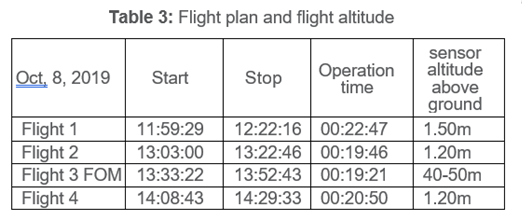
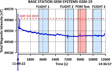
A base station was set up to record the temporal variations of the geomagnetic field during flight operations (Figure 8). On the day of the test flight no significant temporal variations were observed. The time intervals of each flight are shown in Table 3. Interestingly, the total magnetic intensity of the Earth’ magnetic field deviates from the value obtained from the IGRF by about 16nT, which prevails at this time.
The drone was programmed to performing autonomous flights following a set of waypoints that were defined prior to the flight operations. The flight lines are north-south oriented. The line spacing was 2.0m and the length of the lines was 80m. The flight area is 60m wide. 30 lines were flown to cover the area and to collect magnetic data. The size of flight block is approximately one half hectare.
The UAV speed was 4m/s. The distance between sensor and ground was reduced between flights from 1.50m to 1.20m. One flight was needed to cover this area. Two repeated flights were performed over this area. After the second flight the FOM test was performed.
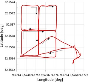
We use a GPS devices (NEO ublox M8N) with singe frequency that outputs raw measurements (carrier phase and code pseudorange) which are post-processed to obtain RTK corrected positions resulting in centimeter-level accuracy in data point positioning. In Figure 9, the flight lines of uncorrected flight lines and the RTK corrected lines are shown. The RTK correction causes a translation of the flight lines by about 1m. Coordinate shifts are also observed in some places, which occur when the GPS data quality is insufficient.


Following procedure was applied to obtain the residual magnetic field intensity (Figure 10):
Step 1
Step 2
Step 3
Step 4
Step 5
Step 6
Application of calibration coefficients to the raw magnetic data to eliminate motion-induced effects from the fluxgate sensor readings
Estimation of Total Magnetic Intensity from the three components Bx, By, Bz from each of the five sensors
Reduction of the local magnetic field obtained from the base station data
Synchronization of magnetic data with GPS position data
Applying the RTK correction and calculating the position of each of the five sensors to generate five magnetic tracks for each flight line.
Gridding the magnetic data and creating a mesh. Creating an isoline plot of the residual magnetic field intensity.
The two following figures display the magnetic tracks of the Pentamag system (Figure 10) and the results of the processed Pentamag data in a 2D isoline plot. The blue dots indicate the locations of metal objects buried in the soil. The yellow dots indicate the locations of magnetic signatures obtained from the Pentamag system.

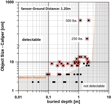
However, only objects above a certain size and up to a certain depth were located. The result of the localization and detection test is summarized in Figure 13.
The data density of the measured area is quite high, but we didn’t achieve 100% coverage. There are still locations with no or coarse data density. Due to gusty winds the multicopter deviated from its predefined flight path. Due to the limited accuracy of the GPS device of about 1.5m the flight line spacing of 2m is within the accuracy of the GPS device. Smaller line spacings are hardly realistic for a single GPS system, but would involve RTK capabilities during flight operation.
The evaluation of the measurement results reveals that objects of a caliber of 3.7cm and at a depth of less than 0.3m are detectable. Larger objects of 10cm caliber can be localized up to about 2m depth. The results are summarized in Figure 13.
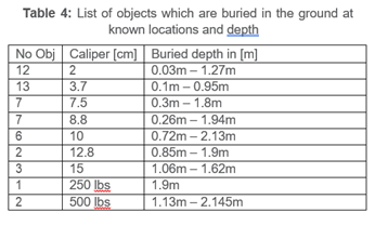
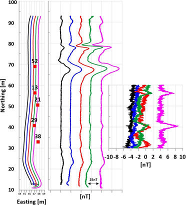
Figure 12 shows five magnetic tracks of flight line 18. Five objects at known locations were overflown. Three of them were clearly located. The sizes and depths are listed in table 5.
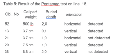
Figure 13 summarizes the results of the Pentamag test on the military test area. 53 objects are buried in the soil at known locations and depths. The test clearly shows that objects of a caliber of 3.7cm and larger are detectable. However, the detectability rapidly decreases with depth. Smaller objects can be detected up to depths of 30cm. Metal objects with a caliber of 10cm and larger can be located up to a depth of 2m. Metal objects of several hundred kilograms can be located at depths of several meters.
Conclusion
In this test we demonstrated that the Pentamag system is capable of locating objects of sizes of 3.7cm. The specific features of this system can be summarized as follows:
- We were able to design and integrate the requisite payload elements associated with such a system. This is obviously subject to power, size and weight limitations imposed by both the UAV and operational needs. Payload elements include magnetometers, data storage and communications infrastructure as well as a power infrastructure (batteries). On board power generation or some hybrid solution is not favoured since it requires additional load and is another source of noise.
- In addition the Pentamag system includes GPS with RTK accuracy, laser altimeter to accurately obtain the flight positions. A laser avoidance systems will be part of the next generation. It is planned to establish a collision avoidance capability in such a manner that a multicopter can fly at elevations of about 1.5 meters at speeds of about five to ten meters per second.
- We designed and built an optimized multicopter which can operate autonomously and can carry this payload for appropriate flight times.
- The collection of high quality magnetic data on this a platform required a) judicious placement of the magnetometer,
- minimization of noise generating components and post acquisition noise elimination, and c) the in-flight calibration which eliminates the magentic signatures due to the multicopter.
- The technical readiness of this prototype was tested in operational environment. This test reveals that metal objects of 3.7cm are detectable.
Acknowledgements
We are grateful to all helpers in the field and to the technical staff, who contributed to the test surveys and to the technical developments. We thank Dr. Holger Preetz (Niedersächsisches Landesamt für Bau und Liegenschaften in Hanover (NLBL)) for his continuous interest in our methodology. He provided the opportunity to perform this test on the military training site. In particular we thank Dr. Christopher Virgil and Christian Kuluecke and Prof. Andreas Hoerdt (TU Braunschweig, Geophysics Institute) for their continuous interest and assistance in the field. We are grateful for their technical support, in particular the integration and deployment of two fluxgate magnetometers.
References
Auster, H.U., Fornacon, K H, Georgescu, E., Glassmeier, K H and Motschmann, U, 2002. Calibration of fluxgate magnetometers using relative motion. Measurement Science and Technology, 13(7), 1124–1131.
Doll, W. E., T. J. Gamey and J. S. Holladay (2001). Current Research into Airborne UXO Detection. SAGEEP Annual Meeting, Oakland, CA.
Gamey, T. J., W. E. Doll, L. P. Beard and D. T. Bell (2003). Analysis of noise coherence in airborne magnetic gradients for UXO detection. 2003 SAGEEP Meeting, San Antonio, TX.
Leliak, P. 1961. Identification and evaluation of magnetic field sources of magnetic airborne detector equipped aircraft. IRA Transactions on airspace and navigational electronics, 8, 95– 105.
Munschy, M., et al., 2007. Magnetic mapping for the detection and characterization of UXO: Use of multi-sensor fluxgate 3-axis magnetometers and methods of interpretation, J. App. Geophys. 61 pp. 168–183.
Nelson, H. H., D. L. Wright, T. Furuya, J. R. McDonald, N. Khadr and D. A. Steinhurst (2004). MTADS Airborne and Vehicular Survey of Target S1 at Isleta Pueblo, Albuquerque, NM, 17 February – 2 March 2003, Naval Research Laboratory.
Author Bios

Johannes B. Stoll
Mobile Geophysical Technologies, GmbH
Celle, Germany
Dr. Johannes B. Stoll has a background in geophysics and electrochemistry and was active in several positions in the Oil&Gas industry and research institutions. He is founder and CEO of Mobile Geophysical Technologies GmbH. He has 25 years experience as an active exploration geophysicist.

Thomas Kordes
Aerialis GbR Stresemann Str. 46
27570 Bremerhaven, Germany
+49(0)471-140 500
Dr. Thomas Kordes, aerospace engineer, UAV operator and co-founder of aerialis. Dr. Kordes has a lot of experience in the management of international aerospace projects and teams. In addition to his management work, he has 20 years professional experience and was responsible for the design, development, and operation of many types of UAVs in international projects

Rolf Noellenburg
Aerialis GbR
Stresemann Str. 46
27570 Bremerhaven, Germany
+49(0)471-140 500
Rolf Nöllenburg, aerospace engineer, UAV pilot and co-founder of aerialis. He is designing, developing and operating fixed wing and rotary wing UAVs for research and commercial use since 2004. In cooperation with MGT, he integrated geo-physical sensor systems into several UAVs within the last 7 years. He is very experienced in adaption and modification of UAVs as well as in soft- and hardware design of the flight control systems. He also gained a lot of operational experience in many international projects.

Anders Jepsen
Founder Exploration For Humanity 1300
Oakmont Drive #4 Walnut Creek, California
94595, USA +1-925-330-9753
Dr. Jepsen has had a 45-year career in various areas of geophysical exploration for minerals, energy and environmental engineering objectives. He is founder of Exploration For Humanity, a nonprofit organization dedicated to combining drones and smart-sensor technology to locate hidden threats such as landmines and unexploded ordnance.
