
Introduction
This article provides an overview of the author’s research conducted on the use of ground penetrating radar (GPR) and an unmanned aerial vehicle (UAV) for mapping buried drainage pipe networks in farm fields. Due to economic and environmental considerations, there exists an important need for effective, efficient, and nondestructive methods for locating buried agricultural drainage pipes. The widespread adoption of subsurface drainage practices to remove excess soil water has enabled the Midwest U.S. to become one of the most productive agricultural regions in the world. A 1985 economic survey showed that several states within the Midwest U.S. (Illinois, Indiana, Iowa, Ohio, Minnesota, Michigan, Missouri, and Wisconsin) had by that year approximately 12.5 million ha of farmland that contained subsurface drainage systems (Pavelis, 1987). Since 1985, a substantial amount of additional agricultural drainage pipe has been installed. Farmers within this region often need to repair drain lines that are not functioning correctly or install new drain lines between the old ones to improve soil water removal efficiency. Whether for system repairs or efficiency improvements, locations of the preexisting drain lines are required; however, in most cases, a map of the original subsurface drainage system installation is no longer available.
Furthermore, subsurface drainage practices can release substantial amounts of nitrate (NO3-) and phosphate (PO43-) from farm fields into adjacent waterways (Sims et al., 1998; Zucker and Brown, 1998). The release of these agricultural nutrients in turn degrade surface water bodies on local, regional, and national scales. Risk assessment of this environmental hazard from the farm field perspective calls for some knowledge of the installed drainage pipe network, including the extent of coverage and spacing distance between drain lines.
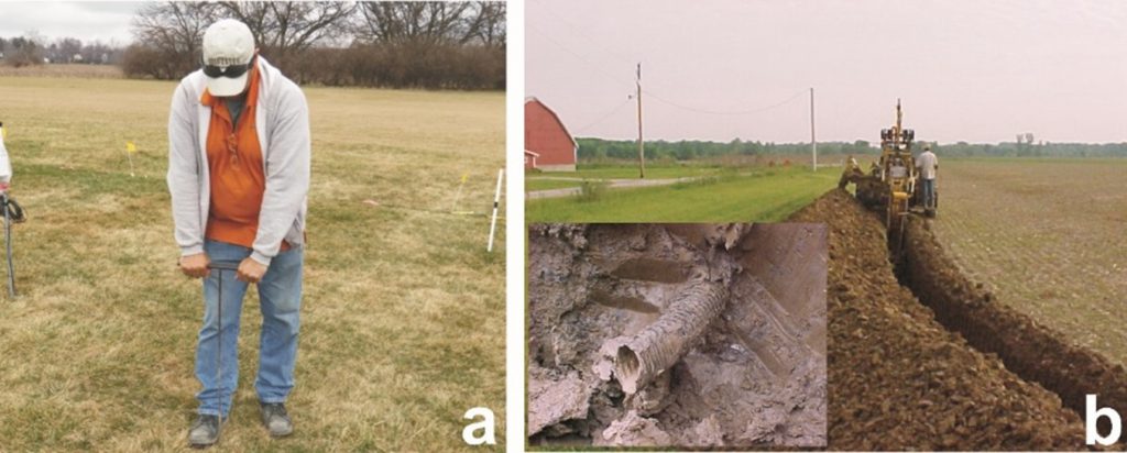
Regardless of whether the need is economic or environmental, finding drain lines with a hand-held tile probe is time-consuming, extremely tedious, and if not careful, can damage buried pipes (Figure 1a). Using heavy trenching equipment is generally effective, but always causes considerable pipe damage requiring costly repairs (Figure 1b). Subsurface drainage system patterns can be complex, thereby further hampering efforts to map drain lines using traditional tile probe or trenching detection methods. Consequently, there is a critical necessity for effective, efficient, and nondestructive drainage pipe mapping methods. Proximal soil sensing or imagery obtained with unmanned aerial vehicles (UAVs) can potentially provide a viable means for mapping these agricultural subsurface drainage systems.
Ground Penetrating Radar Drainage Pipe Mapping
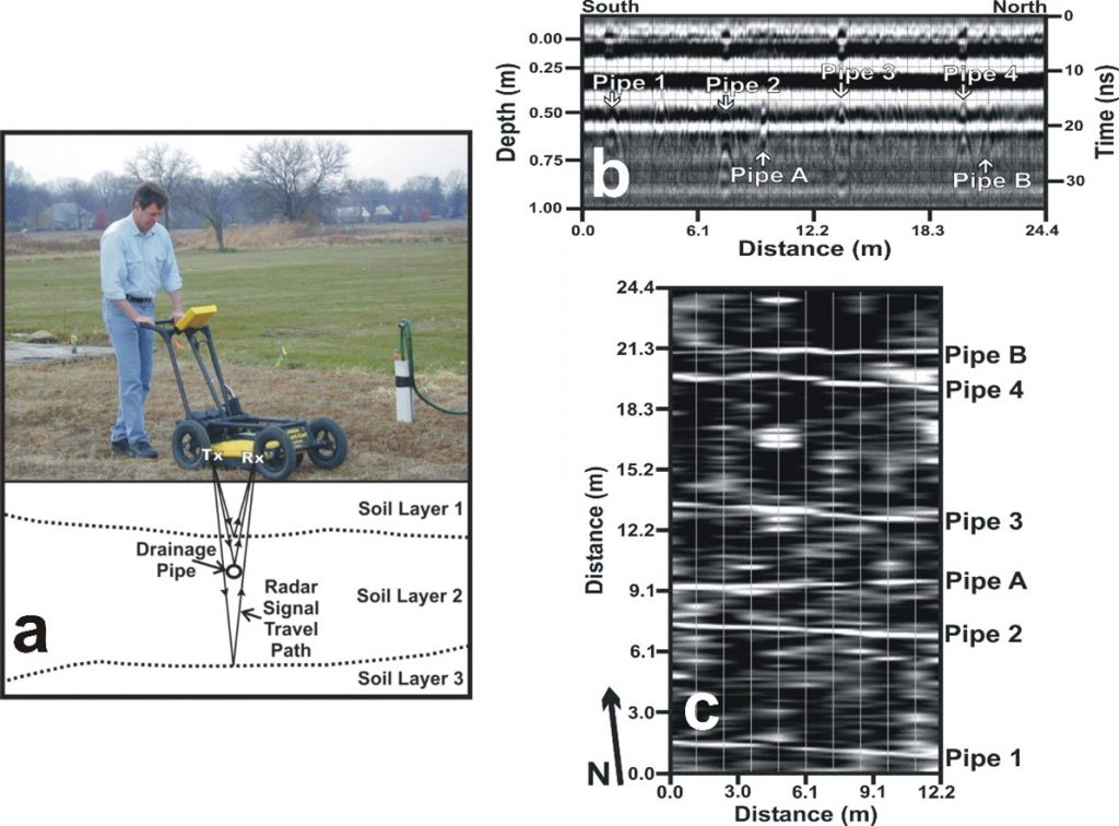
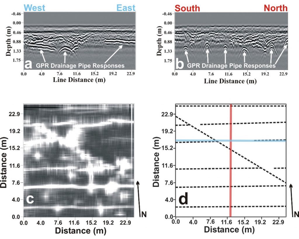
Chow and Rees (1989) demonstrated the use of ground penetrating radar (GPR) to locate subsurface agricultural drainage pipes in the Maritime Provinces of Canada. Allred et al. (2004) tested several near surface geophysical methods (electromagnetic induction, GPR, magnetometry, and resistivity) for subsurface drainage mapping, but obtained success only with GPR (Figure 2). Ground penetrating radar surveys conducted at fourteen southwest, central, and northwest Ohio test plots had an overall drainage pipe detection effectiveness of 74%; with 100% of the pipe found at seven sites, 90% at one site, 75% at two sites, 50% at two sites, and 0% at two sites (Allred et al., 2004; Allred et al., 2005; Allred and Redman, 2010 – see Figure 3). Based on these investigations, GPR was shown to often be to successful in finding clay tile and corrugated plastic tubing (CPT) drainage pipe down to depths of around 1 m in a variety of different soil types. Allred et al. (2005) additionally determined the impact of computer processing procedures, equipment attributes, site conditions, and field operations on GPR agricultural drainage pipe detection. Allred and Redman (2010) showed, given certain shallow hydrologic conditions, GPR capable of locating an isolated drainage pipe obstruction affecting water conveyance functionality. A study by Allred (2013) found substantial differences in the strength of the GPR drainage pipe response for an antenna orientation perpendicular to a drain line versus an antenna orientation parallel to a drain line. Under moderately dry soil conditions, a GPR antenna orientation perpendicular to the drain line provided the strongest GPR drainage pipe response, while under wet soil conditions, a GPR antenna orientation parallel to a drain line provided the best GPR drainage pipe response. Allred et al. (2018a) demonstrated improved drainage mapping efficiency through integration of GPR with Real-Time Kinematic Global Navigation Satellite System (RTK/GNSS) technology. However, even with integrated GPR and RTK/GNSS equipment mounted on an all-terrain vehicle, completing more than 15 ha (40 acres) of a farm field drainage mapping survey in a single day is difficult, so for larger areas, a different method is needed.
Unmanned Aerial Vehicle (UAV) Drainage Pipe Mapping
The soil surface directly over top of a drain line is often drier than the soil surface between drain lines. This phenomenon can be especially true a few days after a large rainfall, because the soil over a drain line is dewatered faster than the soil between drain lines (Smedema et al., 2004). Dry soil surfaces reflect more visible (VIS) and near infrared (NIR) wavelength electromagnetic (EM) radiation than wet soil surfaces (Jensen, 2007a). Panchromatic visible color/grayscale (VIS-C or VIS-G) and multispectral (MS – separate narrow-band blue, green, red, red edge, and NIR wavelengths) cameras can obtain VIS and NIR imagery. Consequently, with VIS or MS cameras, given bare ground conditions outside the growing season, between harvest and planting, lighter shaded dry soil surface features (i.e. increased reflection of VIS and/or NIR radiation), that appear linear, may be representative of drain lines. The Stefan-Boltzmann and Kirchhoff’s laws stipulate that the thermal infrared (TIR) radiation emitted from an object is a function of that object’s temperature and emissivity. Due to the specific heat capacity of water, the soil surface over a drain line may have a different temperature than the soil surface between drain lines. The differences in emitted thermal radiation caused by these temperature differences can be detected with a TIR camera. There may also be emissivity differences between wet and dry soil surfaces that can be detected with a TIR camera (Mira et al., 2007). A wet soil surface soil surface tends to have a higher emissivity value than a dry soil surface (Jensen, 2007b). Therefore, outside the growing season, when bare ground conditions exist, with or without crop residue present, UAV VIS, MS, and TIR imagery can provide a means for mapping subsurface drainage systems.
During the growing season, there often seems to be better crop (corn/soybeans/wheat) establishment and health directly above drain lines, likely from better soil aeration conditions caused by the faster drainage that occurs over a drain line directly after rainfall events (compared to between the drain lines). In fact, crops commonly become first established directly over drainage pipes, which then show up as distinct green lines on VIS-C aerial imagery obtained very early in the growing season. Regardless of the time during the growing season, if the crop has become better established or is healthier over drain lines, then high-resolution UAV VIS imagery, especially VIS-C (rather than VIS-G), can conceivably indicate drainage pipe locations. Multispectral imagery obtained with UAVs is commonly utilized to produce NDVI (Normalized Difference Vegetation Index) and NDRE (Normalized Difference Red Edge) maps, which depict spatial variations in crop establishment and/or health/stress (Jensen, 2016; Sayago et al., 2017), thereby also providing a possible means to delineate drain line locations. Thermal infrared imagery has additionally been utilized to depict spatial variations in crop health/stress (Kullberg et al., 2017; Sepulcre-Cantó et al., 2007; Sobrino et al., 2005). Consequently, UAV VIS-C, MS, and TIR imagery acquired during the growing season can all potentially map agricultural subsurface drainage systems given that the crop is better established and/or healthier over the drain lines.
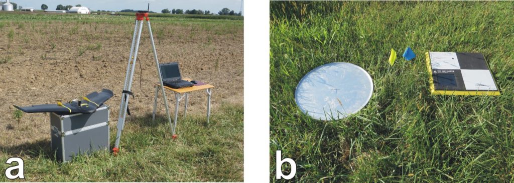
For the UAV drainage mapping investigations conducted by this author, a senseFly SA (Cheseaux-sur-Lausanne, Switzerland) eBee Plus RTK/PPK fixed-wing UAV was employed to carry out VIS-C, MS, and TIR aerial surveys. A fixed-wing UAV can cover larger areas than a multirotor UAV during a single flight, so for this reason, a fixed-wing UAV was chosen for drainage mapping research. The equipment set-up for the unmanned aerial vehicle (UAV) system is shown in Figure 4 and includes the UAV itself (110 cm wingspan), the ground modem antenna (mounted on a tripod), and a computer. The computer had an internal cellular modem that allowed field internet access. The ground modem antenna connected to the computer provided communication between the computer and the UAV. The senseFly SA eMotion 3 software installed on the computer was used to plan/control UAV flight patterns, along with managing the data collected during each survey. During flight, the UAV typically achieved speeds of 37 to 56 km/h (20 to 30 kn). Consequently, during a single 30 min. flight, this UAV could cover 80 ha (200 acres), which is a significant efficiency improvement over GPR for drainage mapping. There were three separate camera payloads utilized in this study; S.O.D.A. (Sensor Optimized for Drone Applications) for obtaining VIS-C imagery with RTK/GNSS positional accuracy, Sequoia for MS imagery, and thermoMap for TIR imagery.
Pix4D SA (Prilly, Switzerland) software, Pix4Dmapper Pro, was employed for initial data processing, particularly “stitching” together of overlapping images obtained during a UAV survey with a particular camera. The end product of this stitching process was a set of VIS-C, MS, and TIR georeferenced orthomosaic image maps of the complete site survey area over which the UAV was flown. Orthomosaic maps were post-processed using ArcMap 10.2 desktop software (Environmental Systems Research Institute, Redlands, California, U.S.A), where annotations were added and the image then saved in a manageable format/size. Further processing was accomplished using the free public access GNU Image Manipulation Program (GIMP) 2.10.10 image editor. This software allowed for adjustment and enhancement of exposure, color levels, sharpness, image size, and resolution.
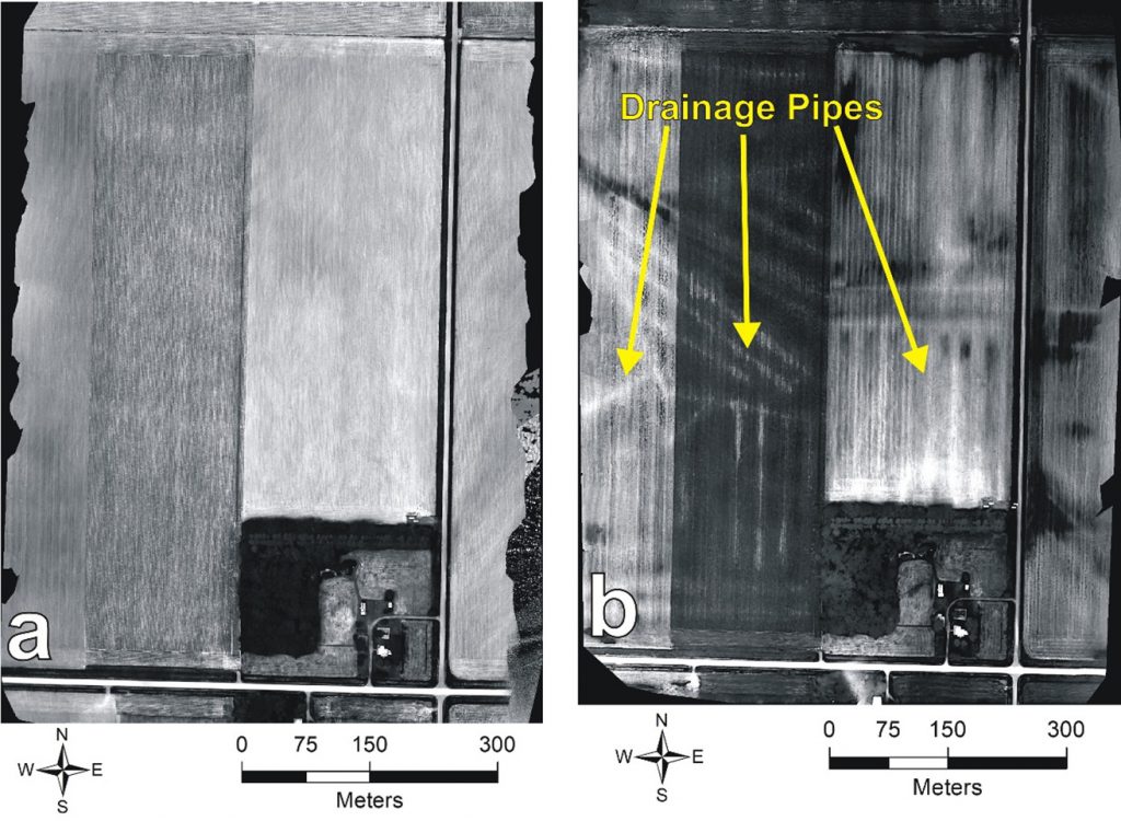

Figure 5. UAV site survey results from farm field in Clay County, Iowa, U.S.A.: (a) TIR orthomosaic map from one day before a 4.2 cm rainfall event (drain lines are not evident), and (b) TIR orthomosaic map from one day after 4.2 cm rainfall event (drain lines clearly depicted). 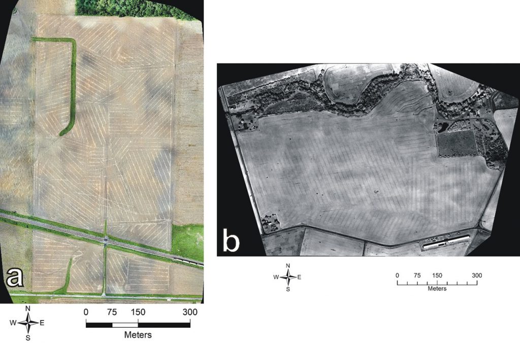

Figure 6. (a) VIS-C orthomosaic of Seneca County, Ohio, U.S.A. farm field under bare ground conditions with drain line locations indicated by lighter shaded linear features, and (b) MS NIR orthomosaic of Ross County, Ohio, U.S.A. farm field covered by a well established soybean crop with drain line locations indicated by darker shaded linear features.
In a preliminary case study by Allred et al. (2018b), a UAV with a TIR camera detected roughly 60% of the subsurface drainage infrastructure known to be present at an agricultural field near Mount Gilead, Ohio, U.S.A. Results obtained from the same field site used by Allred et al. (2018b), found that pairing of RTK/GNSS technology with the UAV TIR survey was essential for accurately locating buried drain lines in the field (Freeland et al., 2019). Williamson et al. (2019) utilized both UAV MS and TIR imagery in a complementary approach to map random drain lines in two conservation tillage farm fields near Harlan, Indiana, U.S.A. Aerial surveys using a UAV with VIS-C, MS, and TIR cameras were conducted by Allred et al. (2020) at 29 agricultural field sites in the Midwest U.S to compare these technologies for drainage mapping. Overall results from this study (Allred et al., 2020) show VIS-C imagery detected at least some drain lines at 48% of the sites (14 out of 29), MS imagery detected drain lines at 59% of the sites (17 out of 29), and TIR imagery detected drain lines at 69% of the sites (20 out of 29). Three key findings, listed as follows, were extracted from the results obtained by Allred et al. (2020). (1) Although TIR generally worked best, there were sites where either VIS-C or MS proved more effective than TIR for mapping subsurface drainage systems. Consequently, to ensure the greatest chance for successfully determining drainage pipe patterns in a field, UAV surveys need to be carried out with all three types of cameras, VIS-C, MS, and TIR. (2) Timing of UAV surveys relative to recent rainfall can sometimes have an important impact on drainage pipe detection results (Figure 5). (3) Linear features representing drain lines and farm field operations can be confused with one another and are often both depicted on site aerial imagery. Knowledge of subsurface drainage system installation and farm field operations can be employed to distinguish linear features representing drain lines from those representing farm field operations. Another key finding emphasized by more recent research is that even though UAV drainage mapping results tend to be better under bare ground conditions, there are cases where drainage network patterns can be effectively mapped with UAVs during the growing season when crops are well established and completely cover the farm field (Figure 6).
Conclusions and Future Research
Both GPR and UAV surveys exhibit promise for mapping agricultural subsurface drainage systems. Of the two, UAV surveys are far more efficient and provide capability for mapping drainage pipe networks in larger farm fields (>15 ha). However, the use of GPR can still be valuable for ground truth of suspected drain line location depicted by UAV imagery. The next step for the research program will be to develop specific guidelines as to when and where this UAV technology can best be employed to map agricultural subsurface drainage systems. To develop these guidelines, additional UAV VIS-C, MS, and TIR surveys will be conducted at farm field sites in Indiana, Iowa, Michigan, Minnesota, and Ohio, specifically chosen so that there will be a wide range of soil types across the sites. Each site will be visited multiple times over a period of several years. With this approach, the range of site conditions (soil type, time of day, within or outside of growing season, soil wetness/dryness, and ground surface characteristics) will be determined under which a particular type of UAV imagery (VIS-C, MS, or TIR) is effective at mapping drain lines.
References
Allred, B. J., Fausey, N. R., Peters, L.Jr., Chen, C., Daniels, J. J., Youn. H., 2004. Detection of buried agricultural drainage pipe with geophysical methods. Appl. Eng. Agric. 20, 307-318.
Allred, B. J., Daniels, J. J., Fausey, N. R., Chen, C., Peters, L.Jr., Youn. H., 2005. Important considerations for locating buried agricultural drainage pipe using ground penetrating radar. Appl. Eng. Agric. 21, 71-87.
Allred, B. J., Redman. D., 2010. Agricultural drainage pipe assessment using ground penetrating radar: Impact of pipe condition, shallow hydrology, and antenna characteristics. J. Environ. Eng. Geoph. 15, 119-134.
Allred, B. J., 2013. A GPR agricultural drainage pipe detection case study: Effects of antenna orientation relative to drainage pipe directional trend. J. Environ. Eng. Geoph. 18, 55-69.
Allred, B., Wishart, D., Martinez, L., Schomberg, H., Mirsky, S., Meyers, G., Elliott, J., Charyton. C., 2018a. Delineation of agricultural drainage pipe patterns using ground penetrating radar integrated with a Real-Time Kinematic Global Navigation Satellite System. Agriculture. 8, e167
Allred, B, Eash, N., Freeland, R., Martinez, L., Wishart. D., 2018b. Effective and efficient agricultural drainage pipe mapping with UAS thermal infrared imagery: A case study. Agric.Water Manag. 197, 132-137.
Allred, B., L. Martinez, M. K. Fessehazion, G. Rouse, T. N. Williamson, D. Wishart, T. Koganti, R. Freeland, N. Eash, A. Batschelet, and R. Featheringill. 2020. Overall results and key findings on the use of UAV visible-color, multispectral, and thermal infrared imagery to map agricultural drainage pipes. Agric. Water Manag. 232, 1-19. https://doi.org/10.1016/j.agwat.2020.106036
Chow, T. L., Rees. H. W., 1989. Identification of subsurface drain locations with ground-penetrating radar. Can. J. Soil Sci. 69, 223-234.
Freeland, R., B. Allred, N. Eash, L. Martinez, and D. Wishart. 2019. Agricultural drainage tilesurveying using an unmanned aircraft vehicle paired with Real-Time Kinematic positioning – A case study. Comput. Electron. Agric. 165, 1-9. https://doi.org/10.1016/j.compag.2019.104946.
Jenson, J. R., 2007a. Chapter 12 – Remote sensing of soils, minerals, and geomorphology. In: Remote Sensing of the Environment, 2nd Edition. Pearson Education, Inc., Upper Saddle River, New Jersey. pp. 457-524.
Jenson, J. R., 2007b. Chapter 7 – Thermal infrared remote sensing. In: Remote Sensing of the Environment, 2nd Edition. Pearson Education, Inc., Upper Saddle River, New Jersey. pp. 243-286.
Jenson, J. R., 2016. Chapter 8 – Image enhancement. In: Digital Image Processing, 4th Edition. Pearson Education, Inc., Upper Saddle River, New Jersey. pp. 273-359.
Kullberg, E. G., DeJonge, K. C., Chávez. J. L., 2017. Evaluation of thermal remote sensing indices to estimate crop evapotranspiration coefficients. Agric. Water Manag. 179, 64-73.
Mira, M., Valor, E., Boluda, R., Caselles, V., Coll. C., 2007. Influence of the soil moisture effect on the thermal infrared emissivity. Tethys. 4, 3-9.
Pavelis, G. A., 1987. Economic survey of farm drainage. In: Pavelis, G. A. (Ed.), Farm Drainage in the United States: History, Status, and Prospects, Miscellaneous Publication Number 1455. U.S. Dept. of Agriculture, Economic Research Service, Washington D.C. pp. 110–136.
Sayago, S., Ovando, G., Bocco. M., 2017. Landsat images and crop model for evaluation water stress of rainfed soybean. Remote Sens. of Environ. 198, 30-39.
Sepulcre-Cantó, G., Zarco-Tejada, P. J., Jiménez-Muñoz, J. C., Sobrino, J. A. Soriano, M. A., Fereres, E., Vega, V., Pastor. M., 2007. Monitoring yield and fruit quality paramaters in open-cnopy tree rops under water stress: Implications for ASTER. Remote Sens. of Environ. 107, 455-470.
Sims, J. T., Simard, R. R., Joern. B. C., 1998. Phosphorus loss in agricultural drainage: Historical perspective and current research. J. Environ. Qual. 27, 277-293.
Smedema, L. K., Vlotman, W. F., Rycroft. D. W., 2004. Chapter 7 – Design of pipe drainage systems. In: Modern Land Drainage: Planning, Design and Management of Agricultural Drainage Systems. A. A. Balkema Publishrs, Leiden, Netherlands, pp. 137-167
Sobrino, J. A., Gómex, M., Jiménez-Muñoz, J. C., Olioso, A., Chehbouni, G., 2005. A simple algorithm to estimate evapotranspiration from DAIS data: application to the DAISEX campaigns. J. Hydrology. 315, 117-125.
Williamson, T. N., Dobrowolski, E. G., Meyer, S. M., Frey, J. W., Allred. B. J., 2019. Delineation of tile-drain networks using thermal and multispectral imagery – Implications for water quantity and quality differences from paired edge-of-field sites. J. Soil Water Conserv. 74, 1-11.
Zucker, L. A., Brown. L. C., 1998. Agricultural Drainage: Water Quality Impacts and Subsurface Drainage Studies in the Midwest, Ohio State University Extension Bulletin 871. Ohio State University Extension, Columbus, Ohio. 40 pages.
