
Jonathan S. Miller, Gregory Schultz, Joe Keranen, Fridon Shubitidze
White River Technologies, Inc.
Lebanon, NH.
Abstract
Over the past 10 years, significant advances have been made in the development of advanced Electromagnetic Induction (EMI) sensors that incorporate multi-axis transmitters and receivers to characterize magnetic field anomaly sources. These sensors provide the capability to discriminate potentially hazardous subsurface Munitions and Explosives of Concern (MEC) from non-hazardous metal debris, thus enabling identification and classification of Unexploded Ordnance (UXO) that require excavation and disposal. The ability to classify these potentially hazardous targets with high confidence allows for lower site remediation costs through reduced excavation of innocuous metal objects (i.e., clutter). Here we explore advanced EMI sensing technologies and methods that may further improve the cost effectiveness of UXO classification. These technologies allow for efficient data collection via dynamic surveys that reduce the amount of time spent acquiring the data necessary to make a dig/no-dig decision. We present results from recent field studies that apply dynamic EMI sensing to achieve high levels of target characterization: from informed source selection (i.e., characterization of anomaly sources for accurate target picking and initial clutter rejection) to one-pass classification (i.e., classification of all anomalies encountered for dig list creation). These results are compiled from both land-based and underwater systems.
Introduction
The effectiveness of advanced EMI sensors for improving the efficiency of munitions cleanup operations has been established with the recent implementation of the DoD Advanced Geophysical Classification Accreditation Program. This program is based on the international standard ISO/IEC 17025:2005 and provides the guidelines for operation of advanced EMI sensors at munitions response sites. The basis for the advanced EMI technology is the incorporation of multiple transmit and receive components that enable characterization of the principal electromagnetic polarizabilities of metal objects (such as UXO, fragmentation, scrap, and other debris), making it possible to classify buried objects as clutter or potential MEC hazards. Since the theory behind the advanced EMI concept has been covered extensively in remote sensing literature, we refer the reader to recent publications on this topic instead of providing a detailed description of the theory here (see e.g., Shubitidze, 2012; Bell, 2013). The current state-of-the-practice for applying advanced EMI at production cleanup sites is to perform the advanced EMI survey as a follow-up “cued” survey to a prior Digital Geophysical Mapping (DGM) survey (www.serdp-estcp.org/Tools-and-Training/Munitions-Response/Classification-in-Munitions-Response). Using this approach, the DGM survey is used as a method to identify magnetic field anomalies corresponding to any metal located on the site. The DGM survey provides approximate locations of these anomalies but does not provide the information needed to make a decision about the type of object corresponding to each anomaly (i.e., debris or potential MEC?). Instead of excavating at every anomaly location, an advanced EMI sensor is brought in to perform static measurements at each one of these cued locations. Because the cued measurement takes only about one minute at each location, it is more efficient than digging and because it can yield the appropriate information needed to make a high confidence decision about the object type, it can greatly reduce (by as much as 90%) unnecessary excavations of scrap metal (Andrews and Nelson, 2011).
Although the cued EMI approach is more efficient than excavating all anomalies, its efficiency could be further improved upon. For example, if the DGM survey can provide more useful information about the anomaly source identity, the number of follow-up cued measurements could be reduced or even eliminated altogether. In other words, if reliable information about target electromagnetic polarizabilities can be obtained from the dynamic DGM survey, this information could support a high confidence dig/no-dig decision on a subset of the anomaly sources. If this subset is small, say 25-40% of the anomalies, then a cued survey could be performed on the remaining anomalies at reduced cost. If the subset is large enough, say 75-80% of all anomalies, then it may be desirable to excavate the remaining anomalies without a cued survey.
Over the last 5 years, we have demonstrated several advanced EMI technologies that have applied the dynamic classification concept to enable informed decisions about the identity of anomaly sources encountered during DGM surveys. The dynamic classification objectives can be categorized as either: 1) Informed Source Selection (ISS), or 2) one-pass classification. ISS applies the polarizability and location information obtained from the data to produce more accurate representations of anomaly source locations (i.e., compared to anomaly locations obtained from a peak detector for example). This information can then be used to better guide excavations or additional cued sensor measurements and/or provide some degree of initial rejection of clutter, such as shallow or surface debris and background noise anomalies. One-pass classification applies the polarizability information obtained from data to classify all anomaly sources encountered as either UXO or non-UXO. This method bypasses the cued survey entirely and produces a dig/no-dig decision using solely the data acquired during the DGM survey.
In the following sections we present examples of dynamic classification applied to UXO surveys conducted in both land and underwater environments. We implemented several different sensor form factors to achieve the desired classification objectives at each site. These examples provide the reader with some idea of the possible benefits of implementing dynamic classification for UXO remediation surveys and indicate the capabilities and limitations of various sensor designs in the context of dynamic classification.
EMPACT Dynamic Discriminator: Informed Source Selection and Clutter Rejection
WRT’s EMPACT Dynamic Discriminator (DD) is an advanced EMI sensor integrated with a man-portable platform designed for dynamic data collection and discrimination of UXO and other Explosive Remnants of War (ERW) from typical battle area metallic clutter. Battle Area Clearance (BAC) operations in post-conflict areas emphasize a reduction in the time required to clear an area, and thus benefit from clutter rejection methods that eliminate time spent digging non-hazardous debris. The EMPACT DD system addresses this need by performing target detection and clutter discrimination functions using data from a single DGM survey. The EMPACT DD system has also been developed for use by personnel who are not experts in geophysical mapping and classification, and features detection and characterization functions built in to the user software that simplify and automate both survey and data analysis processes.
The key components of the EMPACT DD are: 1) an EMI sensing array with an induction coil transmitter and multiple (4-6) triaxial receivers across the 1-meter wide by 0.5-meter long transmitter 2) data acquisition electronics; 3) a Global Position System (RTK-DGPS), 4) an Android phone or tablet; and 5) real-time data processing software that includes Quality Control (QC) functions as well as procedures for final target selection and dig list creation. The processing software implements data filtering, DGPS and EMI data merging, and target detection and characterization algorithms.
Each detected anomaly passes through an automated inversion routine that estimates the location and electromagnetic polarizabilities. Features are extracted from the polarizabilities and used for the discrimination of UXO/ERW from metallic clutter. The characterization process discriminates by: 1) comparing the estimated dipole parameters of each anomaly to a library of known UXO/ERW dipole models; and 2) using polarizability features indicative of the size and symmetry of the anomaly. This discrimination assures the user of properly identifying known UXO while simultaneously assigning objects with UXO-like features a high confidence. Each anomaly is assigned a target identification number and saved with the corresponding DGPS inversion location, depth, and confidence value. An operator uses this “Dig List” to reacquire anomaly locations for subsequent intrusive investigation.
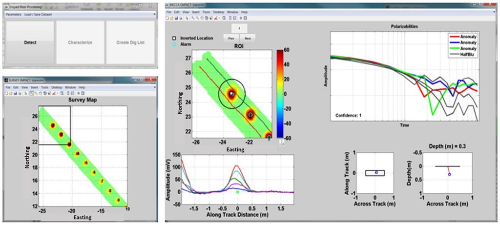
An important element of the automated post-processing software is to ensure that discrimination decisions are presented to the user in a timely and intuitive manner (i.e., an extremely simple and robust, operator-friendly user interface). The inversion routines utilized in the post-processing software can be performed on-site immediately after surveying with little to no input from the user. The post-processing software utilizes three steps (Figure 1). The DETECT step filters the EMI data, merges the filtered data with the GPS information, creates a detection map, and performs anomaly picking. The CHARACTERIZE step implements the physics-based inversion on the data from each detection to create a 3D source location and confidence value. At the end of this step the user may view detailed information for each anomaly or go directly to the next step for creation of the dig list. The CREATE DIG LIST button creates a text file that may be loaded directly into a GPS reacquisition system for staking out targets and beginning the removal process.
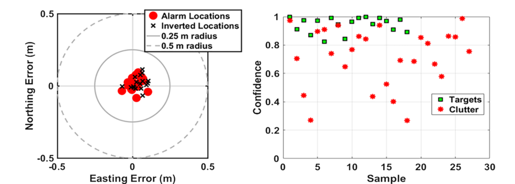
The EMPACT DD has progressed through a number of government validation tests and practitioner demonstrations since 2013. Recently, in the Spring of 2018, the EMPACT DD was deployed in previous battlefields in Southeast Asia. Initial evaluations consisted of QC tests and multiple surveys over a UXO-seeded test area in collaboration with a non-governmental organization (NGO) demining team. Geo-registered UXO “seeds” consisted of submunitions typically found in Cambodia. During NGO evaluations, the location accuracy of our detection and classification algorithms was validated (Figure 2).
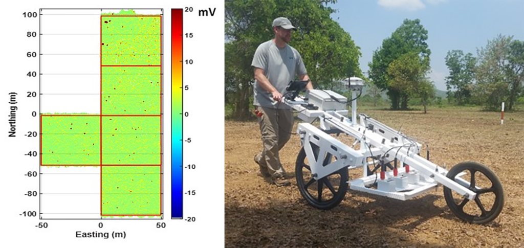
Following the initial evaluations, the system was transported to a UXO remediation operation along the former Ho Chi Minh Trail in Northeastern Cambodia and used daily over a two-week trial collecting survey data over multiple 50 m by 50 m survey grids (Figure 3). Data were processed daily to ensure detection location accuracy and proper classification of QC seeds emplaced in each grid. Follow-on analysis compared the discrimination capability of the EMPACT DD system against a large loop system and a standard DGM system currently in use in UXO remediation operations in Cambodia. Results indicate the EMPACT DD system correctly classified all QC seeds and native UXO in the areas surveyed while reducing the number of digs by 80% and 75% compared to the large loop and DGM systems, respectively.
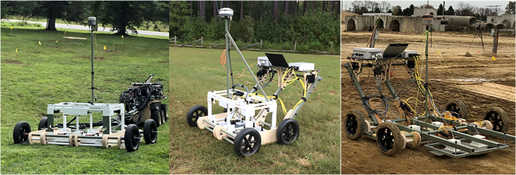
The basic EMPACT architecture is highly modular and has been reconfigured for handheld, man-portable, and vehicle-towed applications. Configurations include a new full 3D implementation: the EMPACT 3D, as well as a deep-search system designed for detection of deeply buried targets (Figure 4).
Flex-EM Crawler Deployed System: Classification for Marine Surveys
Beginning in 2013, we developed and implemented a marine version of the dynamic classification system focused on deployment in particularly challenging nearshore environments such as surf zones, tidal creeks, estuaries, rivers, and lake shores. The Flex-EM array leveraged many of the basic designs for transmitter and receiver sensors and electronics from the EMPACT series units. The configuration of the Flex-EM is designed to operate from fully submerged underwater platforms and specifically from amphibious mobility platforms such as seabottom crawlers or remotely operated vehicles (ROVs). The system was also designed for stable and robust operation in demanding hydrodynamic conditions such as breaking waves and high currents.
When deployed underwater, dynamic classification of UXO requires some special considerations. The form factor and associated hydrodynamic profile of the sensor has important implications on its stability and mobility in currents and waves during survey operations. There is a quantifiable tradeoff between classification performance and hydrodynamic stability control such that drag surfaces (surface area and shape), righting moments, and buoyancy are played off design parameters such as transmitter and receiver coil size, array configuration, and mechanical mounting. This tradeoff generally favors a low profile, flooded sensor head design, with rigid mounting to the mobility system (e.g., remotely operated or autonomous underwater vehicle, seabottom or surface vessel).
Traditionally, classification-level (i.e., advanced) EMI sensors have been successfully deployed using the aforementioned two-step detection/cued approach during land-based surveys. For such surveys, the cued method works because it is a relatively efficient process to reacquire each anomaly location with an advanced sensor on land; however, placing advanced sensors over underwater targets is significantly more difficult. During underwater surveys, non-GPS positioning constraints are compounded by the challenges associated with the actual sensor deployment. Even if accurate position information is achieved (e.g., via a GPS mast or acoustic methods), placement of the sensor in proximity to the contact location requires complicated reacquisition methods. The dynamic mapping and classification applied with the Flex-EM survey data does not require this reacquisition step
The ROV-mounted and crawler-towed versions of the Flex-EM consist of a 1.5 to 2m-wide array mounted on a completely metal-free composite structure. The ROV-based system is integrated directly with the platform structure while the crawler system is towed via a rigid fiberglass boom connected to a three-degree-of-freedom tow point on the crawler. Three different configurations have been tested: i) two transmitters excited in a parallel “aiding” or “opposing” configuration, ii) three transmitters with two side-by-side and fired in opposition for lateral magnetic field excitation and one encompassing transmitter fired separately, and iii) three transmitters fired in sequence independently. The first two configurations enable a relatively low profile sensor head with effective two-dimensional magnetic field excitation (the third dimension being illuminated via relative offset from a target’s position as in the EMPACT DD operational concept). Unlike the first two configurations, the third configuration (three independent transmitters) requires little or no reliance on relative positions between scans.
Positioning and navigation options for the crawler-towed system include both GPS-based (e.g., mast for shallow water operation) and underwater positioning technologies such as inertial navigation and ultra-short baseline (USBL) or long baseline (LBL) systems. Although the tow platform is coupled to the crawler through a rigid tow bar, the tow point has 3 rotational degrees of freedom to allow motion over roll, pitch, and yaw angles. Therefore, we have an absolute angle encoder at the tow point to measure the yaw (azimuth) and an inertial measurement unit on the tow bar that provides roll and pitch angles. These measurements can be combined with those acquired on the crawler platform itself to generate relative orientation between the two bodies.
In trials in 2016, we implemented the 3D Flex-EM array towed from the SeaView Systems (Dexter, Michigan) SurfROVer bottom crawler at the U.S. Army Field Research Facility coastal test site in Duck, North Carolina (Figure 5). The primary objective was to validate the integration of the 3D EM array sensor tow, navigation and control system, and the robotic crawler mobility platform in challenging nearshore environments. System performance was assessed through analysis of the towed Flex-EM array, position, and attitude data collected during execution of several dry (beach) and submerged surveys (in both surf zone and intertidal sound). Stability and efficient mobility of the crawler platform over a range of nearshore environments has led to a new ability to acquire data for detection and potential characterization of UXO in these areas.
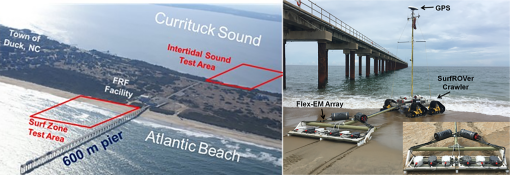
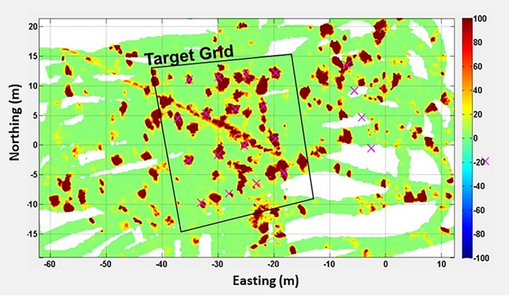
During our tests, target grids of simulant UXO were established in both the surf zone and intertidal sound areas that straddle the Outer Banks barrier island chain in this area. Target emplacement and ground truthing in the surf zone proved very challenging due to weather conditions during our testing time frame. Figure 6 shows an example map of EM data responses over shore-parallel transects near our target grid. Overall, the towed EM array tracked the crawler with an approximate 9 meter radius for nominal turns.
Subsequent tests were conducted in the intertidal Currituck Sound at water depths between 1 and 3 meters and directly adjacent to the Atlantic Beach surf zone site (Figure 5). The bottom substrate at this site was primarily fine sand and mud – a significant contrast to that in the surf zone in terms of bottom contact conditions. Surveys were conducted over the target area and all targets were detected. Significant opportunities for clutter reduction testing were also presented as the test area was cluttered with numerous metallic debris items as shown in the anomaly map (Figure 6).
Target classification was conducted by analyzing the EM anomalies identified from the multiple 3-axis receiver responses. We used data aggregated from consecutive soundings along adjacent survey transects to ensure the target received the required multi-axis field illumination from the transmitter to produce accurate polarizabilities for analysis (i.e., the change in transmitter offset from the target produces a change in the field angle of incidence on the target).
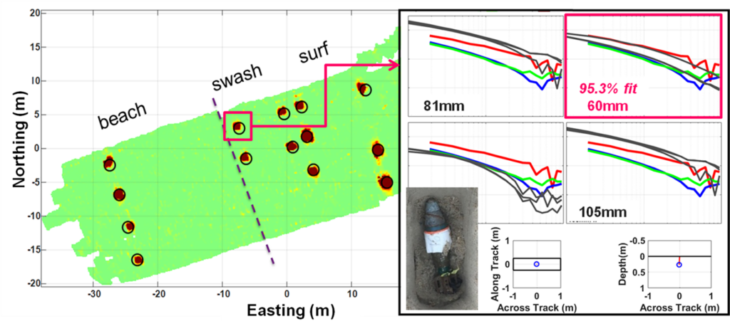
The post-processing software implements filtering, position and EM data merging, and detection routines to provide anomaly locations. The dipole-based inversion routine, as in the EMPACT systems, minimizes misfit between dipole model outputs and the Flex-EM data. This method directly supports the discrimination of targets from potential clutter items using a match fit to TOI libraries (Figure 7). During the Duck surf zone trials, we applied this discrimination method to achieve 100% detection of TOI in the test grid with a clutter rejection rate of 48%. Target location accuracy was achieved with a 9 cm mean error (28 cm standard deviation).
OPTEMA: One-Pass Dynamic Classification
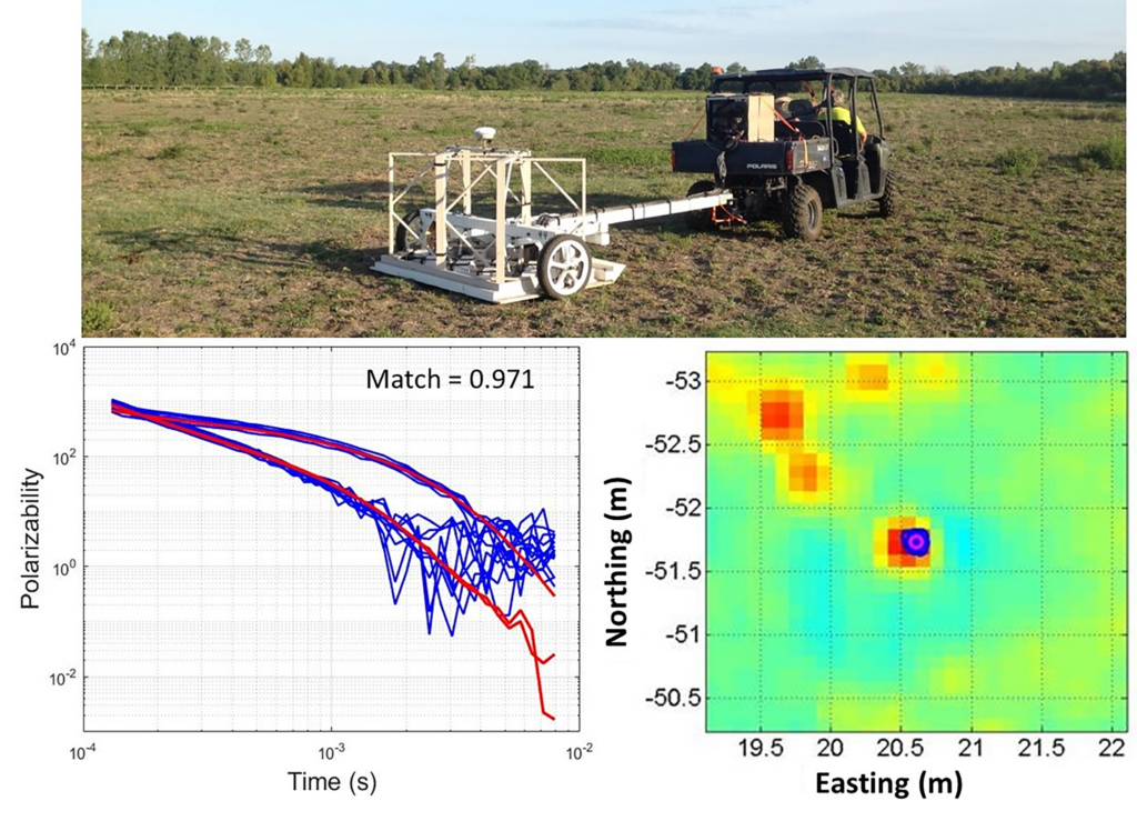
We recently demonstrated a vehicle-towed system for one-pass dynamic classification of UXO. The OPTEMA sensor comprises an array of five transmitters and fourteen 3-axis receivers distributed across a 1.8-meter swath to enable characterization of target electromagnetic polarizabilities. The basis for the one-pass approach is the ability to recover accurate classification features (i.e., polarizabilities) from the dynamically acquired data such that a high confidence decision can be made regarding an object’s type as either a Target of Interest or a non-TOI (e.g., scrap metal). To achieve this high confidence, the OPTEMA functions as a “3-D” sensor, cycling through each transmitter to produce three approximately orthogonal fields beneath the sensor array during each sample period. Because a complete transmitter cycle is performed every 100 milliseconds, the OPTEMA performs a 3-D sample at a rate of 10 Hz, which corresponds to approximately 5-6 centimeters of travel distance. This approach produces a high density of 3-D measurements, augmenting the ability to resolve smaller targets.
Data from each 3-D measurement are inverted for the target electromagnetic polarizabilities, producing a group of polarizabilities corresponding to each source encountered during the survey (i.e., several 3-D measurements are acquired in proximity to any source covered by the sensor in the survey area). The source features cluster in both physical 3-D space, as well as in the polarizability space. In other words, the inversion of dynamic data produces target location and polarizability estimates that are similar for each unique source. This clustering can be used to identify, localize, and ultimately classify each source encountered. Figure 8 shows an example of location and polarizability clusters recovered from OPTEMA data. The location cluster is plotted on the electromagnetic anomaly map showing the physical location of the source estimate. The polarizability cluster is plotted against a set of library polarizabilities with a match-to-library value displayed (1 – high confidence TOI, 0 – high confidence clutter).
Data collection procedures for the OPTEMA are similar to procedures used for other advanced EMI sensors operated in dynamic mode. Quality checks are performed regularly throughout the survey in the form of Instrument Verification Strip (IVS) tests, which are performed 2-3 times per day. Dynamic noise levels (i.e., measurements of background noise variation throughout the site), measurement line spacing, and down-track sample spacing are evaluated for each survey file prior to departing the site. With these quality checks in place, it is possible to perform classification of a large volume of data after the survey is completed, without the need to keep equipment or personnel on-site to potentially reacquire data. This quality process makes dynamic surveying an efficient method for implementing Advanced Geophysical Classification (AGC).
Under the Environmental Security Technology Certification Program (ESTCP) live site demonstration effort, we performed a 4-acre dynamic survey at part of the former Southwestern Proving Ground (SWPG) near Hope, Arkansas. The principal objective of this survey was to detect and classify munitions as small as 20-mm projectiles amongst similarly sized clutter items while completing the survey of the 4-acre recovery field section in a minimal amount of time. We performed the survey over the course of a day and a half, resulting in an approximate 3-acre per day production rate. On-site quality control of the data revealed some data collection issues including a GPS fault (a grazing cow had moved the base station at one time), resulting in a few survey line recollects performed the following day. After analyzing the data quality and confirming all quality objectives were met, we demobilized the equipment and performed the final classification analysis off-site.
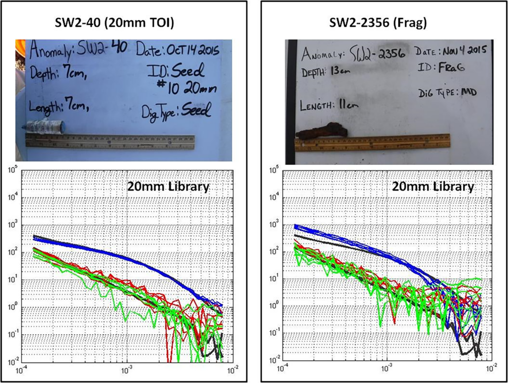
Target pick analysis of the 4-acre area revealed an anomaly density of ~2500/acre. Three smaller focus areas within the site were selected for intrusive investigation of approximately 2000 anomalies in total. We performed classification analysis and ranking of these anomalies. Our analysis comprised an automated clustering and ranking based on polarizability match to TOI libraries. Polarizability clusters were identified by groups corresponding to the unique source locations on the anomaly map. These clusters were then compared to a library polarizability database of known TOI and assigned a ranking based on the library match value. An analyst reviewed the list and identified targets for training data (i.e., ground truth information acquired from intrusive investigation). The greatest challenge for this site was the large number of clutter items that were similarly sized to the 20-mm projectile. Training data were effective for establishing an appropriate threshold to reject much of this clutter. Figure 9 shows an example of a 20-mm projectile and a similarly sized piece of clutter identified from training data. Distinguishing between these objects was critical to achieving effective classification at this site.
After reviewing the training digs, we selected a library match threshold that we believed would eliminate much of the small clutter while retaining all of the 20-mm TOI on the dig list. Third party scoring of our dig list revealed this approach was effective. All TOI encountered were correctly classified as such with approximately 82% of the clutter eliminated from the dig list. Furthermore, at the 100% efficiency operating threshold (i.e., the point where maximum clutter rejection can be achieved with no missed TOI) we achieved 95% clutter rejection.
We performed a second, recent OPTEMA survey as part of a field study for the U.S. Army Corps of Engineers (USACE) at the former Fort Ord, CA. The principal objective of this field effort was to establish the effectiveness of one-pass dynamic classification to identify sensitively fuzed munitions, specifically smaller 40-mm projectiles. These items are particularly challenging for EMI sensors due to their relatively low ferrous metal content. The study design included a large number of these 40-mm projectiles emplaced as seed items amongst the native TOI and clutter present in the field study area. Seed items were emplaced at a range of depths to test the detection capabilities of the sensor.
We completed a dynamic survey of approximately 10 acres over a period of 4 days, resulting in an approximate 3-acre per day production rate (similar to that achieved at the SWPG). Again, we completed the initial data quality analysis on-site and performed the final processing and classification and analysis off-site after equipment demobilization. Due to time constraints and site availability following the survey, intrusive results were limited to a relatively small sample. Accordingly, seed results were used primarily to establish classification performance.
We selected a 2-acre sub-area within the field study area to perform classification and ranking of all anomalies. Within this region, we identified approximately 8000 unique anomalies, which we subsequently classified using the aforementioned automated cluster and ranking method. Because the seed ground truth information was used to assess performance, no analyst intervention was applied. The ranking was established entirely by the automated clustering and matching to a full TOI library database.
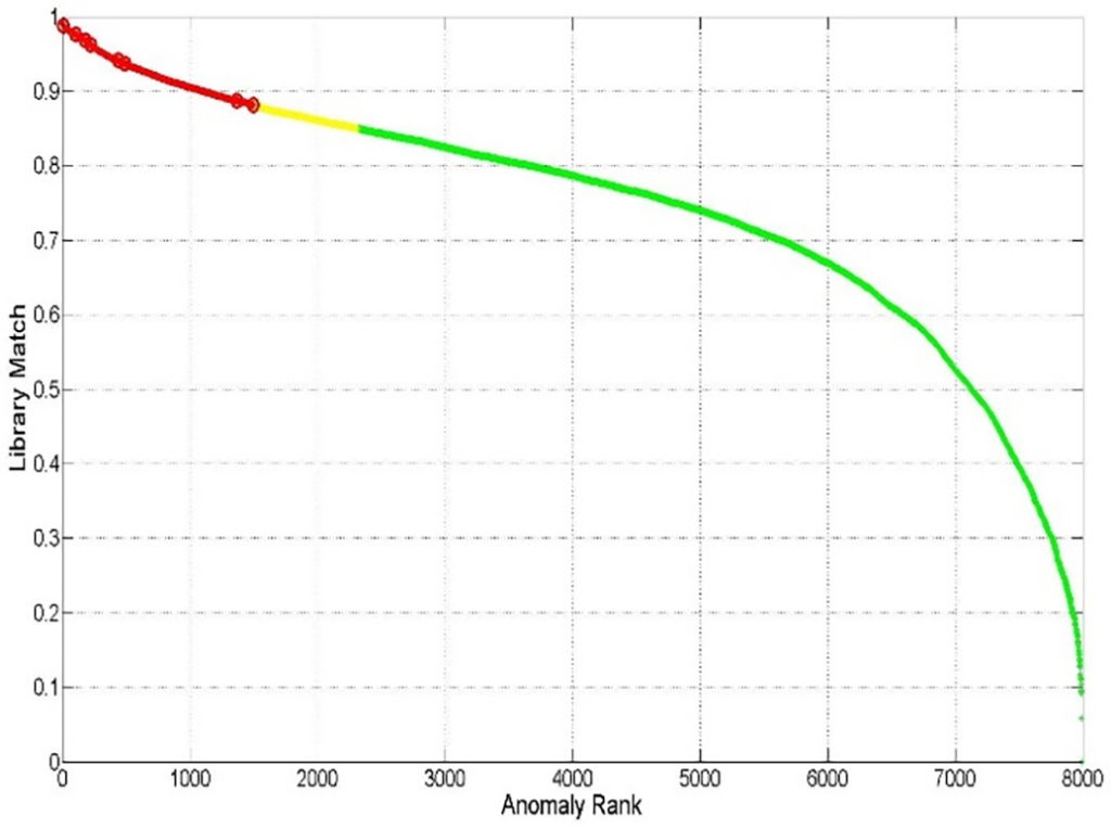
The sub-area contained 12 seed items at depths of up to 18 inches below ground surface. The automated ranking correctly classified 8 of these seed items emplaced at depths ranging from 5 – 10 inches. The 4 missed seeds were below the detection threshold of the sensor and were at depths ranging from 11 – 18 inches. Figure 10 shows the automated ranking order of the detected anomalies. The last detected seed on the list was ranked 1497/7975 and produced a match value of 0.88 (approximate 85% clutter rejection rate). The automated stop dig threshold was set to a match value of 0.85, which we estimate corresponds to an approximate 75% clutter rejection rate.
These two OPTEMA surveys demonstrate the capabilities of the system for enabling effective one-pass classification. Both field studies were conducted in high density areas with small munitions present and showed that dynamic classification methods can be applied effectively to resolve these challenging TOI while maintaining cost effective clutter rejection levels.
System Performance Summary and Conclusions
The aforementioned three systems demonstrate the benefits of applying dynamic classification as part of the AGC process. Each system was designed for specific classification objectives that included basic clutter rejection in BAC operations (EMPACT DD), classification of munitions in the underwater environment where sensor positioning and placement is challenging (Flex-EM), and one-pass classification of UXO including small munitions in high density environments (OPTEMA). Results from our field studies have shown that reliable classification of TOI is possible while maintaining clutter rejection levels that improve the overall efficiency of the AGC process. Regardless of whether subsequent cued measurements are implemented, the ability to identify a substantial portion of clutter during the DGM stage will have a significant impact on lowering the costs of production UXO cleanup projects.
Acknowledgments
The authors would like to acknowledge the Environmental Security Technology Certification Program, the U.S. Army Corps of Engineers, and the U.S. Army for supporting development and testing of the EMPACT DD, Flex-EM marine crawler, and OPTEMA systems. Additional thanks to members of Kemron, Gilbane, and Naeva for providing field support during the OPTEMA demonstration at the former Fort Ord.
References
- Andrews, A., and Nelson, H., 2011, Implementing advanced classification on munitions response sites: a guide to informed decision making for project managers, regulators, and contractors: Environmental Security Technology Certification Program (ESTCP) Final Report
- Bell, T., 2013, Tensor invariant processing for munitions/clutter classification: Strategic Environmental Research and Development Program (SERDP) Project MR-2100 Final Report
- Shubitidze, F., 2012, A complex approach to UXO discrimination: combining advanced EMI forward models and statistical signal processing: Strategic Environmental Research and Development Program (SERDP) Project MR-1572 Final Report
Author Bios

Jonathan Miller
Jonathan Miller is a Senior Engineer at White River Technologies. He obtained a B.S. degree in Physics from Bates College and an M.S. degree in Mechanical Engineering from the University of Vermont. His research interests include application of magnetic and electromagnetic sensing to detection, subsurface characterization, and infrastructure monitoring. He is currently performing several projects involving integration of these sensor modalities with airborne and undersea platforms. Mr. Miller also serves as a Project Geophysicist on Advanced Geophysical Classification projects for TPMC-WRT under their ISO 17025 quality program.

Gregory Schultz
Gregory Schultz is the Chief Technology Officer at White River Technologies. He received a B.S in Earth and Atmospheric Physics and a Ph.D. in Geophysics from the Georgia Institute of Technology. His research interests include: electromagnetic sensors and integration, coastal and marine geophysics, hydrogeophysics, geophysical site characterization, target recognition and statistical signal processing, and inverse modeling of frequency-domain EMI and resistivity data. Dr. Schultz was the Principal Investigator for a project to develop a marine crawler-based EMI system. That project recently received a Project-of-the-Year Award from the Environmental Security Technology Certification Program.

Joe Keranen
Joe Keranen is a Senior Research and Development Scientist at White River Technologies. He obtained a B.S. in Electrical Engineering from Michigan State University and an M.S. in Acoustics from Pennsylvania State University. His focus is on development of UXO detection, estimation, and classification algorithms as well as advanced munitions sensing and multi-sensor data fusion approaches. Mr. Keranen’s current work involves the development and application of expert analysis software that allows for full exploitation of advanced detection and classification sensors for production UXO site remediation. He has also worked to demonstrate the potential for productivity increases that could be realized by incorporating this advanced technology as part of production protocol.

Fridon Shubitidzeis
Fridon Shubitidzeis a Senior Research Physicist at White River Technologies and a Research Professor with the Thayer School of Engineering, Dartmouth College, Hanover, NH. He received the degree of Diploma radio physicist (M.S.) from the Sukhumi branch of Tbilisi State University (TSU), Sukhumi, Republic of Georgia, in 1994 and the Cand.Sci. (Ph.D.) degree in radio physics (applied electromagnetics) from TSU in 1997. His current work interests focus on development of advanced EM sensing technologies (from 0 Hz up to GHz) for detecting and classifying buried explosive hazards on land and in underwater environments. In 2011, Dr. Shubitidze and his group received the Munitions Response Project-of-the-Year Award given by the Strategic Environmental Research and Development Program for developing and demonstrating advanced EMI models and algorithms for UXO detection and classification.
