
Alexander Prikhodko
Andrei Bagrianski
Petr Kuzmin (Expert Geophysics Limited)
Abstract
Recent advances in the airborne electromagnetic technologies based on naturally occurring audio-frequency magnetic fields (AFMAG) are discussed. The technical solutions applied in the MobileMT platform allow it to detect targets of any shape and structures of any orientation, provide a depth of investigation that exceeds any airborne EM method with controlled field sources, and make the system sensitive in both conductive and resistive environments. Four field examples from historical and active mine sites were presented which demonstrate the exceptional exploration capabilities of the MobileMT technology in conditions usually considered problematic for airborne EM due to industrial noise, conductive overburden, differentiations in resistive environments, or rough terrain.
Keywords: mine sustainability, resource expansion, airborne electromagnetics, AFMAG.
Introduction
The long-term viability of mines and mine infrastructure requires expansion of the reserve/resource inventory. Brownfield, or near-mine exploration, is generally an effective and low-risk way to keep a mine sustainable, but any deposit has its natural boundaries. Contemporary advanced exploration technologies which provide new levels of information about the surrounding mine area are making it possible to grow the resource base through new discoveries in the same or similar adjoining geological structures. In this paper we describe a new concept of the AFMAG method — airborne EM MobileMT technology. MobileMT technology overcomes many limitations of the previous platforms of the method and EM systems with controlled primary field sources. The MobileMT’s technical solutions make it possible to explore resistive environments even with slight differentiation in resistivity, to penetrate thick and conductive overburden, to collect reasonable data even near industrial noise sources, and produce quality data in rough terrain conditions. The system is sensitive to geoelectrical boundaries of any direction, discrete targets, and continuous structures. The MobileMT depth of investigation always exceeds the depth of investigation of systems with controlled sources near-surface.
Main Airborne EM Methods
The main airborne electromagnetic methods are listed in Table 1 – Airborne EM principles. The methods differ in the primary field sources which induce currents in the subsurface geology. The estimated depths of investigation (DOI), shown in the table, are approximate and conditional depending on rock conductance and the controlled transmitters’ technical features, but the general ratios between the different methods’ DOI are close to reality.
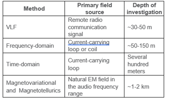
The MobileMT technology belongs to the “Magnetovariational and magnetotellurics” natural field methods in the audio-frequency range with a depth of investigation exceeding all other methods.
The MobileMT Method and the Main Technical Parameters
The basis of the MobileMT technology is close to that of the ground magnetotelluric method, but there are some specific advantages to the airborne method. The system consists of a stationary surface base station
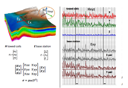
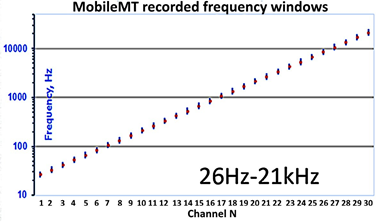
measuring independent main and reference electrical signals intended to provide bias-free and denoised orthogonal horizontal component data (Figure 1a), and the towed airborne receiver for measurement of variations in the three magnetic components of the natural EM field (Figure 1b). The variations of the electromagnetic field are measured in the frequency range 26 Hz – 21 kHz, then digitized and recorded at 74 kHz to produce a representative data series (Figure 1) for high-quality data synchronization and processing. The Fast Fourier Transform technique is applied to the merged recordings with calculation of six admittance matrices on the different time bases and in different frequency bands. As a result of modular computation of the matrices’ determinants as rotation invariant parameters, apparent conductivity is calculated for each frequency window as a main parameter of the MobileMT mapping (Figure 1).
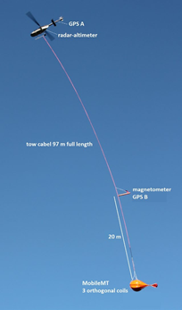
All the main components of the MobileMT platform during a survey are shown in Figure 2.
The whole measured frequency range is divided into windows (channels) during the data processing. Typically, 20 or 30 windows are formed depending on the natural signal and external noise characteristics (Figure 3). After data processing, informative and noise-free windows are selected for further representation and data inversions.
The following technical solutions are possible as a result of the technology’s high performance in mineral exploration tasks and its abilities to overcome limitations of other platforms and principles. In particular:
– impedance-type data provides sensitivity to absolute resistivity differences, not just to relative contrasts;
– the measurement of the total magnetic field vector (through three orthogonal components) means that no attitude correction is required and all related physical and analytical noise sources are excluded;
– the total field measurements provide the system sensitivity for any direction of geoelectric boundaries – from horizontal to vertical;
– the wide range of measured frequencies provides a range of depth of investigation from the surface to depths of more than 1 km;
– due to its very low noise floor the MobileMT data could be split into smaller frequency windows which provide high in-depth resolution, data selection, and industrial noise localization.
MobileMT Depth of Investigation
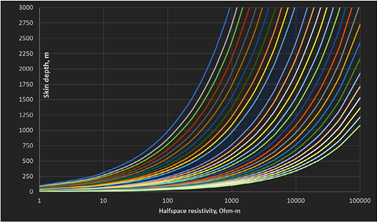
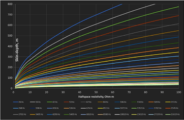
Depth of investigation of the MobileMT technology can be estimated based on the “skin” depth parameter (Spies, 1989)
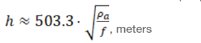
where h — depth of investigation in units of m; ρa – apparent resistivity in units of ohm∙m; ƒ – frequency in Hz.The skin-depth calculated for the MobileMT-range frequency channels depending on the halfspace resistivity is presented in Figure 4 and Figure 5. The latter illustrates the significant MobileMT DOI estimate even in a conductive environment.
Field Examples of the MobileMT System’s Capabilities
The field examples below demonstrate the effectiveness of MobileMT and its capabilities in the variety of conditions found in historical and currently active mining districts.
La Plata historical mining district
This MobileMT data example is from an area of Colorado with a very rugged terrain and the receiver height sometimes exceeding 300 m above the surface. The La Plata survey area is a historic gold-silver high-grade mining district with significant mineral production in the past. Currently, exploration in the district is focused on the potential for disseminated bulk-tonnage and stockwork porphyry-hosted copper mineralization (Metallic Minerals Corp). A MobileMT survey was flown for deep resistivity mapping under the conductive overburden and in the rugged relief conditions. The MobileMT data was processed and confirms that apparent conductivity taken from multi-component natural electromagnetic field data does not depend on the receiver terrain clearance in a wide range of
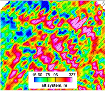
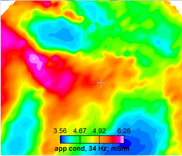
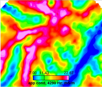
Figure 6 – a part of La Plata survey area a) Receiver terrain clearance
b) apparent conductivity low frequency c) apparent conductivity high frequency
elevations. As shown in the presented maps (Figure 6), there is no manifestation of the receiver flight height in the range 15-337 m above the surface in the low and high frequency data.
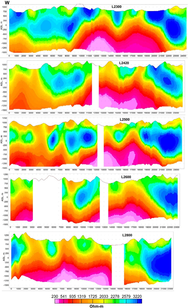
Dukat ore field mine area
Dukat is currently the world’s third largest silver deposit and the largest gold-silver deposit in Russia. The epithermal-type Au-Ag ore field occurs in the central section of the Omsukchan riftlike trough (~150 km in length) along a regional North-South fault system. The framework of the depression is intruded by numerous granitoid polyphase stocks and plutons, porphyry and dykes (Levitan, 2008). The central part of the ore field contains a dome-like structure (granite-granodiorite pluton) which is intersected by drill holes to a depth of 1200 – 1500 m below the surface. The main elements of the Dukat deposit that govern the ore bodies’ structure are subvertical zones consisting of systems of sub-parallel shear cracks, zones of mylonite along faults, individual large fractures, tree-like dykes, and veins (Levitan, 2008).
The airborne MobileMT EM technology was able to identify 1) the deep dome structure as the main controlling factor of the Au-Ag mineralization system; 2) other deep dome structures, and potential for new discoveries beneath them; 3) the subvertical fault zones as feeding fluid transport channels from the upper contact of the deep magmatic bodies to the near-surface host rocks together with following alteration and potential ore zones.
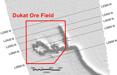
Currently four deposits are under mining operations and the challenging factor for an airborne EM survey over the area is the EM interference from the industrial sources of electromagnetic noise. The MobileMT survey, although affected by the power line noise, was still able to produce good data for analysis and inversions revealing the geological response within a couple hundred meters from the sources of interference. Unfortunately, high-voltage power lines usually pose a challenge for data collection in a wider range of frequencies.
The MobileMT survey lines crossing the Dukat ore field are displayed over the power line monitor shaded map in Figure 7. Line 2600 crosses an underground mine. Resistivity sections along the lines are presented in Figure 8. The blanked areas hide distortion caused by the industrial noise. As seen from these sections, the system’s exploration capabilities are preserved quite close to the power lines.
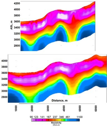
Tien-Shan metallogenic belt
The next case is from the Tien Shan metallogenic belt with orogenic- (or mesothermal-) type gold deposits. This example demonstrates the MobileMT system’s capability for deep resistivity mapping under conductive overburden. The gold deposits are structurally controlled and the MobileMT system was able to detect the controlling mineralization structure inside and below the conductive (<100 Ohm∙m) overburden with ~400 m thickness (Figure 9). The lines were flown just several hundred meters from an active open pit mine.
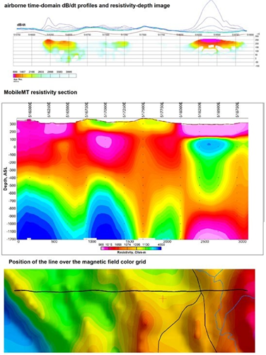
Aylmer Property (Sudbury, Northern Ontario)
The IOCG Aylmer Property is located northeast of the Sudbury Igneous Complex, the known world-class mining camp in an under-explored polymetallic gold district. The copper-gold mineralization is expected to be associated with a zone of deformation and alteration (Transition Metals, 2020). The airborne MobileMT survey has been conducted to highlight evidence of a buried system at depth. A part of the property was previously flown with a time-domain system (Fiset, 2011). Because the area is quite resistive, the time-domain data only shows some near-surface conductors associated with river and valley sediments without getting transient response from deeper layers (Figure 10, top profiles and a section). The MobileMT system is sensitive to resistivity differentiations in much higher ranges and is able to detect conductive and resistive units and structures within the 1.5 km depth range, along with the near-surface conductors (Figure 10, middle section). MobileMT detects a deep fault, or a dyke in the center of the line, which is visible in the magnetic field as well (Figure 10, bottom map). There is a copper showing on the surface over this structure (Transition Metals Corp., 2020).
Conclusions
Based on the measurements of the natural electromagnetic fields in the audio-frequency range, the MobileMT airborne exploration technology is an effective tool for extending the
life of historical or currently active mine sites. It is capable of bringing new and detailed information about the geological subsurface in wide ranges of depth and resistivity.The technology has a great depth of investigation (1-1.5 km on average), revealing both near-surface and deep structures. It is sensitive to resistivity differentiations in low and high resistivity ranges in any direction of geoelectrical boundaries, and in many cases it is able to get reliable information close to industrial noise sources.
References
Fiset N., 2011, Report on a helicopter-borne Versatile time- domain electromagnetic (VTEM-plus) and horizontal magnetic gradiometer geophysical survey. Geotech Ltd., 65 p.
Levitan G., 2008, Gold Deposits of the CIS, Xlibris Corp., 356 p. Metallic Minerals Corp. La Plata Property overview. https://www. metallic-minerals.com/projects/laplata-1/property-overview/
Spies B.R., 1989, Depth of investigation in electromagnetic sounding methods. GEOPHYSICS, VOL. 54, NO.7; P. 872-888.
Transition Metals Corp., 2020, IOCG-Aylmer properties highlights. http://transitionmetalscorp.com/images/support/projects/ PRES-Aylmer-Property.pdf
Author Bios

Alexander Prikhodko
Chief Geophysicist and Vice-President Expert Geophysics Limited.
21-1225 Gorham St., Newmarket, ON, L3Y 8Y4
Canada
Alexander has been associated with the airborne geophysics industry since 2005 (Aeroquest Limited and Geotech Ltd.) holding management positions as Regional General Manager, Data Interpretation Manager, and Director of Geophysics and working on exploration projects for diverse commodities in regions over the world. His professional career included the chief geophysicist position in a gold-platinum mining company for more than ten years. In this role, his expertise was extensively used in its mineral exploration programs’ borehole, ground, and airborne geophysics. He holds a MSc and PhD in geophysics, and Executive MBA.

Petr Kuzmin, Ph.D.
Chief Scientist
Expert Geophysics Limited
21-1225 Gorham St., Newmarket, ON, L3Y 8Y4
Canada
Petr Kuzmin has over 40 years of experience in the development of ground and airborne TDEM, MT, and IP methods, equipment, and software. Working for Geotech Ltd., Canada, from 2000 until 2009, Dr. Kuzmin was the principal designer of the award winning systems VTEM, ZTEM, and AirMt. Since 2009, Dr. Kuzmin has completed a number of successful developments: ground AFMAG, ultra-fast airborne TD (HiRes), airborne VLF system, an airborne navigation system, a high accuracy magnetometer counter, and the MobileMT. Dr. Kuzmin holds a doctorate in Geophysics, has authored nearly 20 patents, and published over 40 technical papers.

Andrei Bagrianski, Ph.D., P.Geo.,
President
Expert Geophysics Limited
21-1225 Gorham St., Newmarket, ON, L3Y 8Y4
Canada
Andrei Bagrianski has over 35 years of professional experience in the acquisition, processing, and interpretation of airborne and ground geophysical data for a wide range of applications. From 2002 to 2016, he was Chief Operating Officer and General Manager at Geotech Ltd. Andrei has been directly involved in contracting, organizing, and supervising hundreds of airborne geophysical surveys on all continents except Antarctica. Andrei has extensive experience in international field work including projects in Australia, Brazil, Bolivia, Colombia, Ecuador, Peru, Botswana, Malawi, South Africa, Libya, USA, Canada, Russia, Kazakhstan, Kyrgyzstan and India.
