
This article was originally published in the “Proceedings of the DFI 45th Annual Conference on Deep Foundations, 2020 – ONLINE”. It is being reprinted herein with the permission of the Deep Foundations Institute. For information about DFI, its publications and programs visit, www.dfi.org.
By William P. Owen1 , William M. Dalrymple²![]() and Benjamin S. Rivers ³
and Benjamin S. Rivers ³
1 California Department of Transportation, Sacramento, California
Email: bill.owen@dot.ca.gov
² California Department of Transportation , Sacramento, California
Email: william.dalrymple@ dot.ca.gov
³ Federal Highway Administration, Atlanta, Georgia,
Email: @dot.gov
Published 06/30/2021
ABSTRACT
For the California Department of Transportation (Caltrans), geophysical applications have played an important role as part of a successful multidisciplinary approach to subsurface characterization for the design of high value structures. Since at least the 1950’s, geophysical methods have been deployed to guide the exploration drilling program and to maximize the return on drilling investment by increasing the amount of data obtained from test borings. Geophysical applications saw increased use beginning in the 1990’s, during the seismic retrofit of the state’s toll bridges and the replacement of the west span of the San Francisco-Oakland Bay Bridge. Over the intervening years, increases in computing power and increasingly sophisticated commercial off-the-shelf software applications have allowed Caltrans to leverage advancements and perform geophysical investigations of increasing complexity and scale. Ultimately, the goal of these efforts is to maximize return on investment, whereby increased investigation costs at the design phase are offset by reduced uncertainty regarding subsurface conditions, leading to reduced cost overruns related to change orders and unforeseen site conditions during construction. These objectives are consistent with the recent Every Day Counts (EDC) initiative to incorporate Advanced Geotechnical Methods in Exploration (A-GaME) into routine engineering practice. Caltrans is an implementation partner of the A-GaME initiative, and Caltrans’ practices represent a model toward the institutionalized geophysical site characterization practices for other transportation organizations. The authors provide a retrospective on 70 years of experience with geophysical applications for transportation infrastructure, with examples and observations on potential future direction of the industry.
Keywords: geophysics, geotechnical, transportation, California
INTRODUCTION
Project change orders related to differing site conditions account for as much as 7% of total transportation agency spending on construction, and up to 50% of the delays and cost escalations experienced during construction (Boeckmann and Loehr, 2016). The most common reasons for differing site conditions include unanticipated high groundwater, mischaracterized subgrade, and unanticipated rock encountered during excavation (ibid. p. 33).
The use of geophysical methods to augment drilling, sampling and laboratory testing for design of structure foundations is not a novel concept. However, despite a century of development it remains underutilized for many civil engineering projects and inconsistently applied across state transportation departments (DOTs). Research into reasons for that phenomenon identified lack of understanding as the primary factor influencing underutilization (Sirles, 2006). Over a decade later, not much has changed in that regard (Rosenblad & Boeckmann, 2020). In a nationwide effort to improve subsurface characterization for transportation projects, the Federal Highway Administration is actively promoting advanced geotechnical investigation methods, including geophysical methods, for routine application to project design (FHWA, 2018). Under its Onramp to Innovation initiative, FHWA has introduced the Every Day Counts program (EDC) to advance a culture of innovation in the transportation community. As they state (FHWA, 2019):
Through this State-based effort, FHWA coordinates rapid deployment of proven strategies and technologies to shorten the project delivery process, enhance roadway safety, reduce congestion, and improve environmental outcomes.
Under Round 5 of EDC, FHWA introduced Advanced Geotechnical Methods in Exploration (A-GaME; FHWA, 2019). For this program, Caltrans contributes as an institutionalized user of geophysical A-GaME technologies to assist in development of incentives and implementation strategies for increasing the user base of these technologies among other state DOTs.
The A-GaME outreach has increased awareness among state DOT’s on the value provided to projects by geophysical methods. At present, however, only a handful of state DOTs have routinely incorporated them as part of their investigation suite for cost-effective foundation design (FHWA, 2019). The California Department of Transportation (Caltrans) is one of those DOTs with significant experience in its application. Here, we provide a brief history of our 70 years of geophysics experience leading to its institutionalization within the geotechnical program. We also highlight two significant projects where successful application provided significant contribution to project planning or design.
Organization
In its current configuration, Caltrans’ Geophysics and Geology Branch is part of the Geotechnical Services division. In that capacity, the branch acts as an internal consultant to three Geotechnical Design Offices
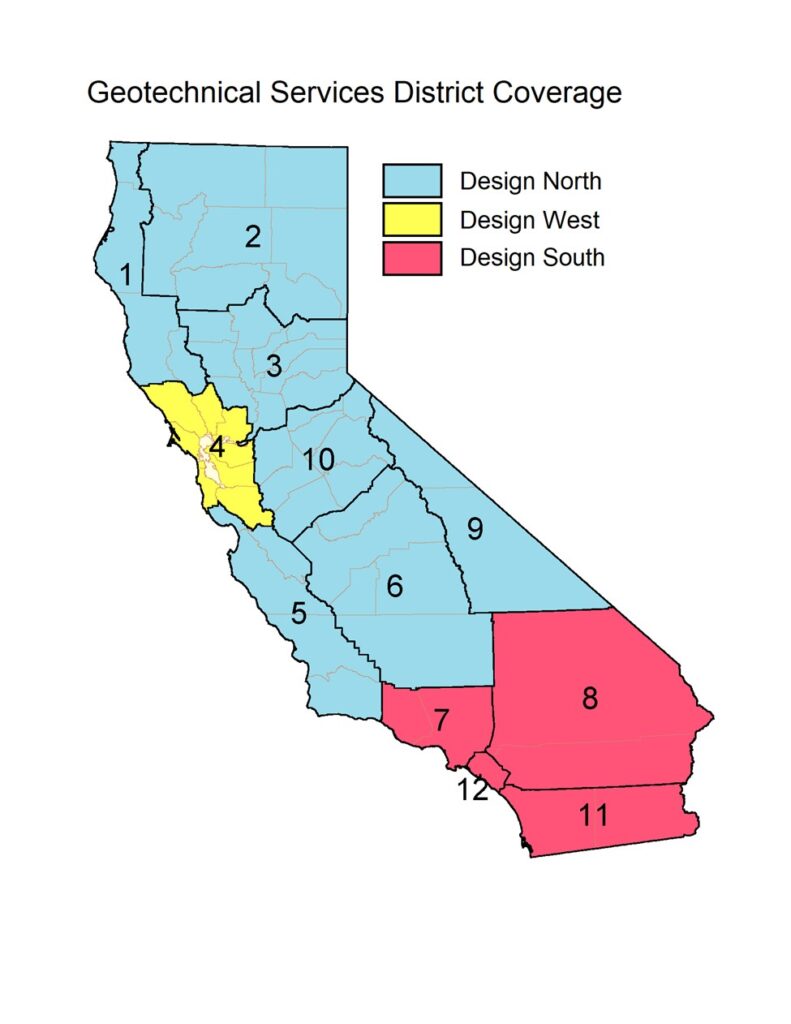
Fig. 1. Caltrans Geotechnical Services geographic service territories. Numbers correspond to District offices and boundaries as outlined. The Geophysics and Geology Branch services all twelve districts across the entire state. From Caltrans (2018).
who are assigned specific territories in the state (Fig. 1). The Geotechnical Design offices, by primary function, provide structure foundation and roadway geotechnical engineering design for the State Highway Network. The Geophysics and Geology Branch provides in-house support to those offices, performing a variety of geophysical investigations that provide in-situ soil and rock properties to aid roadway and foundation design. Additional services, such as pavement investigations and utility locating, are also provided to other Caltrans offices as needed. Contract geophysical services are also available to meet peak workload demand and provide specialty services not otherwise performed in-house.
Caltrans uses geophysical methods both to guide the exploration drilling program and to expand subsurface information beyond the drilled locations. We also use borehole geophysical methods to maximize the return on drilling investment by increasing the amount of in situ data that can be obtained from test borings. By increasing the amount of subsurface information available, we allow better structure design, more accurate project bids and reduction of unforeseen foundation conditions.
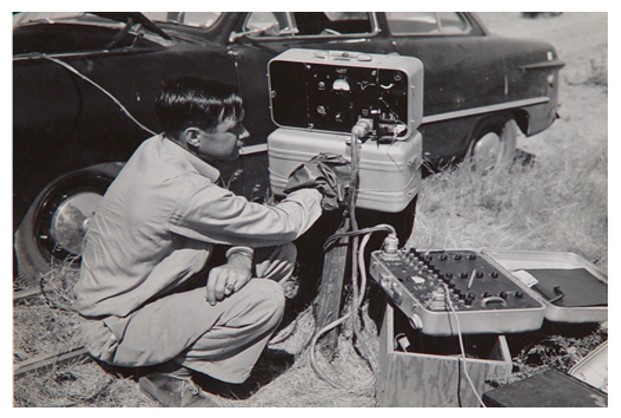
HISTORICAL PERSPECTIVE, 1950-1990
Though not extensively used until the 1990’s, geophysical applications have a long history at Caltrans. The earliest documented geophysical survey was a seismic refraction investigation performed in the early 1950’s for design of the roadway excavation at the approach to the second Carquinez Bridge, at the north end of San Francisco Bay (Fig. 2). Archived project files also show that seismic refraction and electrical resistivity methods were applied to geotechnical problems at least as far back as the early 1960’s. Research into use of seismic velocity data for determining rippability and estimating earthwork factors was completed in the 1970’s. In the 1980’s and early 1990’s, attempts were made at shear wave refraction studies, and downhole interval velocity logging for shear wave measurements was introduced. However, the scope and quantity of this work was limited and relatively static into the early 1990’s. Knowledge and application of geophysical investigations was limited to a few geologists and technicians who were primarily tasked with
engineering geology investigations for roadways and structure foundations. Their geophysics work was performed ad hoc in support of those functions.
EXPANSION OF USE, 1993-2000
Increased application of geophysical tools for structure design began around 1990 (Owen, 2000). The significant event marking this change was the October 1989 Loma Prieta Earthquake. Extensive damage in the San Francisco Bay area from that event highlighted the vulnerability of California’s transportation infrastructure to moderate and large seismic events. This vulnerability was shown again 4 years later and 400 miles farther south, when America’s costliest earthquake to-date struck near Northridge in southern California.
Besides causing structural damage and loss of life, substantial economic losses from the Loma Prieta earthquake were also incurred by disruption of the state’s transportation system. Those economic losses were felt statewide, and highlighted the need for systematic hardening of road, highway and rail structures to minimize damage and disruption of the transportation network from seismic events. To that end, Caltrans launched its Seismic Retrofit Program, an ambitious initiative designed to inspect and evaluate every structure in the State Highway Network for seismic risk and, where necessary, repair and retrofit or replace those structures to minimize that risk. The program enlisted the combined efforts of engineers, geologists and geophysicists to inspect structures, evaluate geologic conditions at their foundations, collect geophysical data, derive appropriate site seismic response models, and evaluate structure designs for ability to resist anticipated seismic loads.
For geophysics, the Seismic Retrofit Program demonstrated a clear need for personnel trained and experienced in a variety of geophysical methods, and it marked the first time at Caltrans where geophysical methods were systematically applied on a large scale. In the program, the primary task of the geophysicist was to acquire seismic velocity data critical for developing ground response models. Both compressional and shear velocity data were used in the modeling process. Those data were collected through borehole geophysical logs, a process where probes are sent down a borehole and measurements are made at discrete intervals. Initially, logs were collected using a locking downhole geophone and a surface shear wave source. These interval velocity logs were both time consuming and limited in depth. In 1992, logging efficiency significantly improved with the acquisition of a downhole shear wave logging system.
In addition to velocity logging, electrical resistivity and natural gamma logs were also recorded at larger structures, to assist in geologic interpretation and for the development of geologic cross sections. For most of the duration of the Seismic Retrofit Program, shear wave logging was performed both in-house and via service contractor, but electrical resistivity logging was outsourced entirely. This added logistical complexity by requiring two separate logging crews to mobilize to the same job site, with one crew on standby while the other logged. When the structure in question was over water, as with our major toll bridges, additional cost was incurred in having to place an entire drilling barge on standby for the duration of logging operations. In 1995, with our resistivity logging contract due for renewal at the end of the fiscal year and continued funding for the retrofit program in question, we considered numerous cost-saving measures, one of which was assumption of the electrical resistivity logging function. From that analysis, we observed that performing this function in-house would realize significant savings and quickly recoup the initial equipment investment. In July 1996 the resistivity logging contract was allowed to expire, and Caltrans assumed in-house responsibility for all geophysical logging functions. That decision marked the beginning of a formal geophysical service function within Caltrans.
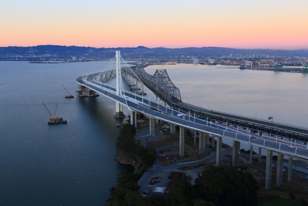
Case #1, San Francisco-Oakland Bay Bridge Replacement
The largest project for the Toll Bridge Retrofit Program was replacement of the east span of the San Francisco-Oakland Bay Bridge (Fig. 3). Given the scope of the project and the Department’s in-house commitments to numerous other projects within the Seismic Retrofit Program, all foundation investigation work for the replacement span was performed under contract.
The project involved two major segments: the main span at the western end and the skyway to the east. Although the focus here is on the skyway segment and is limited to the geophysical work, the geotechnical investigation for the entire east span remains the largest effort of its kind in the history of Caltrans. The geotechnical data collected to support the foundation design for the skyway alone was significant (Fugro-Earth Mechanics, 2001a):
- 44 offshore borings, cored through sediment and up to 200 feet into rock, including:
- In situ downhole vane shear tests and Cone Penetrometer Tests,
- P & S Suspension logging for primary and shear wave velocity measurement,
- Electrical resistivity, caliper and natural gamma logging,
- Acoustic televiewer logging in bedrock,
- Onboard laboratory testing of core samples:
- Unconfined Compressive Strength,
- Direct Shear Strength,
- Point Load Index,
- Compression Index,
- Undrained Shear Strength,
- 77 additional CPT soundings (to infill and correlate test boring information),
- 130 linear kilometers of 2-D seismic reflection data,
- 640 linear kilometers of 3-D seismic reflection data:
Concurrent multibeam bathymetric/echo sounder survey (Fig. 4).
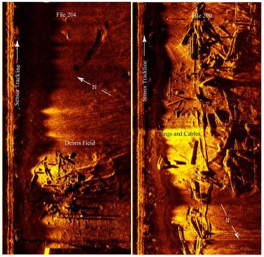
Additional sidescan sonar surveys (Fig. 5) were performed for archaeological resource investigation and to evaluate bottom hazards for construction (Allen, 2000).
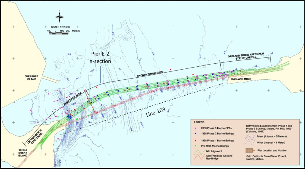
Fig. 4. Bathymetric map and alignment, SFOBB east span replacement. Seismic reflection profile (Line 103) and geologic cross-section at Pier E-2 shown on Figs. 6 and 7. From Fugro-Earth Mechanics (2001b).
The Main Span section for the replacement SFOBB east span was designed as a single-tower, self-anchored suspension bridge. The central pylon for the tower was to be anchored into an underwater ridge of Franciscan Formation bedrock that extends eastward from Treasure Island. The eastern pier (the western end of the skyway) would rest on large diameter piles tipped into marine and terrestrial sediments at the edge of a large, infilled paleochannel of unknown extent. Therefore, the geophysical surveys had several complementary objectives:
- Borehole Geophysics:
- Provide in situ P- and S-wave velocity for structure seismic design,
- Provide in situ measurement of attitudes of bedrock discontinuities to evaluate, foundation stability for the center tower,
- Estimate in situ material properties (e.g., density, porosity),
- Stratigraphic correlation,
- QC for logs of test borings,
- Marine Seismic Reflection:
- Evaluate alignment alternatives,
- Bathymetric information,
- Trend and depth of bedrock,
- Paleochannel delineation.
Development of Stratigraphic Models
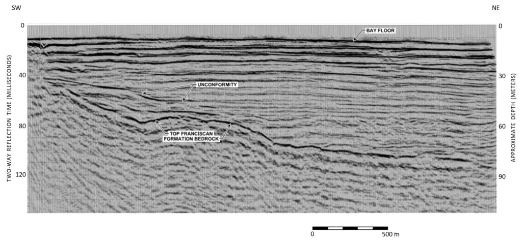
Synergistic evaluation of test borings, geophysical logs and reflection data aided in developing a comprehensive model of the stratigraphy in the vicinity of the preferred alignment. Figure 6 provides an example of reflection data used to help define the top of Franciscan bedrock along the alignment alternatives. Figure 7 shows examples of velocity logs acquired at the east pier (Pier E-2). (Data locations are shown on Fig. 4.)
Delineation of Franciscan Ridge
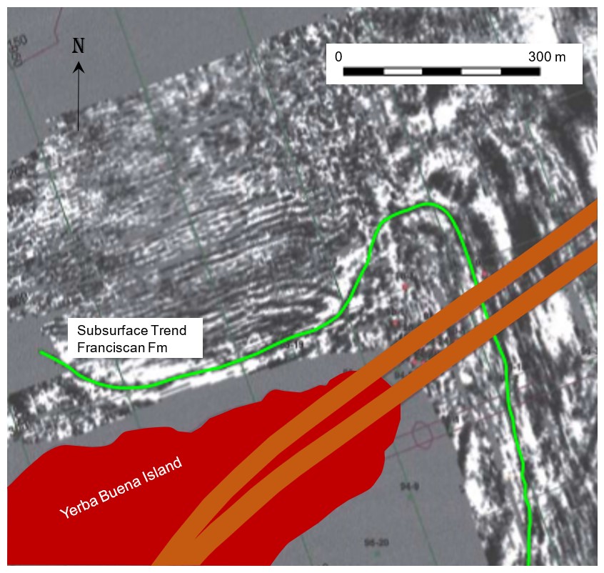
Figure 8 provides a plan view of the 3D reflection results at Treasure Island. The data show the trend of the Franciscan undersea ridge angling northward from its exposure on the island. The results of this work indicated that the main span tower foundation would be located on the steeply dipping ridge. The lateral stability of the foundation at that location was of significant concern. Inspection of the reflection data discounted the presence of faulting or a preexisting slide mass within the Franciscan basement in the vicinity of the main span tower location, removing assumptions that would have resulted in unnecessary and costly design provisions.
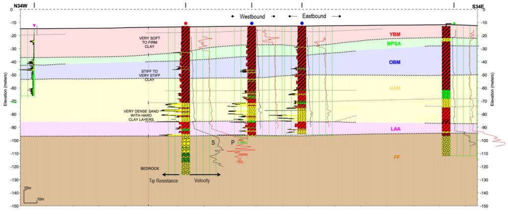
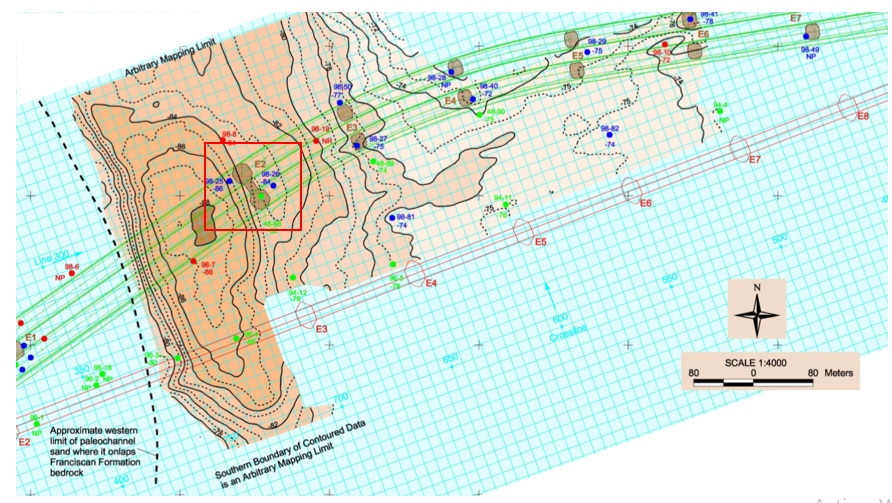
Evaluation of Paleochannel Fill
Of notable interest was the extent of the infilled paleochannels and their potential impact on the east pier location for the main span (and the westernmost end of the skyway segment). These paleochannels formed during Quaternary low sea level stands and infilled during high-water interglacial periods and Recent sea level rise. Initial concern was the implication that Holocene clay infill of the channels would provide insufficient pile capacity and inadequate lateral load deformation response (Fugro-Earth Mechanics, 1998). Subsequent analysis of the reflection data and additional drilling in the vicinity of Pier E-2 (the east pier) confirmed the existence of a thick sequence of stiff marine clays overlying alluvial sand infill beneath and east of the modern channel (Fugro-Earth Mechanics 2001b). West of Pier E-2, the western boundary of the mapped sand onlaps the Franciscan Formation bedrock ridge (Fig. 9). To the east, the sand thins and grades into silty sand and clay. Soil testing confirmed adequate pile capacity could be achieved within the sediments, but difficult driving was anticipated within the paleochannel sands, with the potential for pile refusal before adequate pile embedment could be achieved (Fugro-Earth Mechanics 2001c). As a result of improved understanding of actual subsurface conditions, alternative pile designs were subsequently proposed for improved constructability.
Integration into Geotechnical program 1998-2017
Beginning in 1998, the Geotechnical Services division at Caltrans expanded to accommodate increased project workload. At the same time, advancements in geophysical equipment and software were improving work efficiency and allowing the branch to tackle projects of larger scope with only a modest increase in crew size. By March of 2000, a geophysical services unit was staffed with the sole mission of providing geophysics support for the division. The increase of in-house capacity allowed the newly formed Geophysics and Geology Branch to expand services offered and to take on projects of larger scope and complexity.
Concurrent with formation and expansion of the geophysics program was development of manuals and guidance that codified geophysical investigations into Caltrans’ geotechnical design process. The first of those occurred in 2012 with publication of the ARS Online module for Caltrans’ Seismic Design Criteria (Caltrans, 2012). There, use of geophysical methods was explicitly defined to determine Vs(30) for calculating site specific acceleration response spectra. Later, the role of geophysics as part of a geotechnical investigation was defined and set as policy with publication of the Geotechnical Investigations chapter for the Caltrans Geotechnical Manual (Caltrans, 2017). With that publication came official recognition of geophysics as part of the geotechnical program at Caltrans.
Case #2, SR-710 Tunnel Investigation
Beginning in 2008, Caltrans conducted a joint investigation for a proposed extension of I-710 in Los Angeles County. Proposed design of the extension called for a tunnel to be constructed under the heavily urbanized surface. Subsurface conditions along five proposed alignments were to be evaluated (Fig. 10).
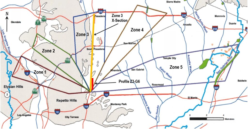
Fig. 10. Location of I-710 Tunnel Corridor Study. Investigation zones labeled as shown. Locations shown for Zone 3 Alignment cross section (Fig. 11) and seismic reflection profile Z3-G6 (Fig. 12). From CH2M Hill (2009).
The investigation program utilized both in-house and contract services. The field investigation included surface geologic mapping, mud rotary test borings, and geophysical surveys. Data acquired during this preliminary investigation included the following (CH2M Hill, 2009):
- 25 test borings, including:
- P & S Suspension logging for primary and shear wave velocity measurement,
- Electrical resistivity, caliper and natural gamma logging,
- Acoustic televiewer logging in rock,
- Laboratory testing of core samples,
- Pressuremeter testing
- Packer tests for formation permeability
- 17 P-wave seismic reflection profiles,
- 78 multichannel analysis of surface wave (MASW) tests for shear wave velocity measurement.
The in-situ data were used to define geologic and hydrogeologic conditions that could impact tunnel construction, including sediment and rock distribution, rock engineering properties, fracturing, water inflow, folding and faulting, and naturally occurring formation gas. Geology was highly variable among the five corridors, with the North-South routes possessing the more challenging conditions, including large hydraulic head differences across active faults. Shear wave velocity information was used to estimate ground seismic response that might impact tunnel design.
Development of Stratigraphic Models
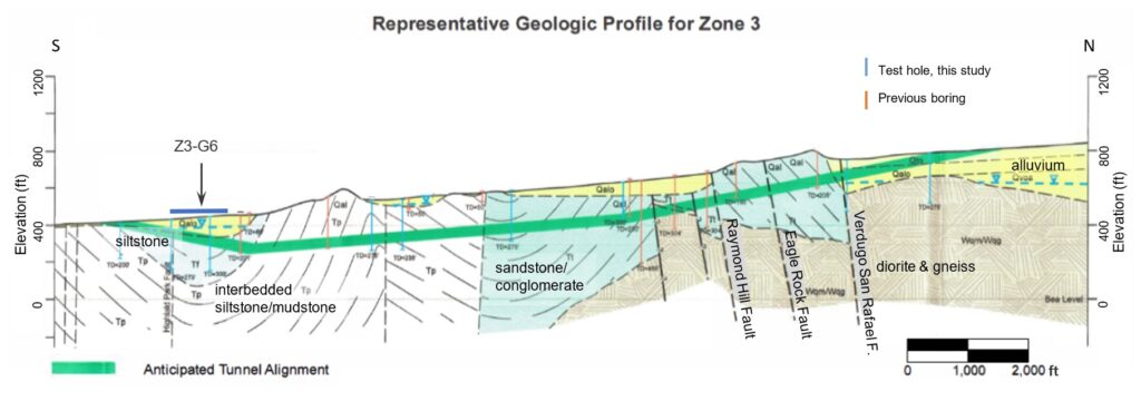
Reflection profiles, logs of test borings and geophysical logs were used to refine the existing geologic mapping of the area and develop updated stratigraphic cross sections for each corridor zone to determine formations and structures that might be encountered during tunneling. Figure 11 provides an example of anticipated geologic conditions for one tunnel alignment scenario. For this example, predominant rock types at the tunnel elevation consist of folded mudstones, sandstones and conglomerates for most of its length, with unconsolidated alluvium at the portals. Changes in bedding attitude would be encountered as the alignment crosses the limbs of anticlines. Several significant faults would also be intersected. At one fault in particular (the Raymond Hill Fault), the fault zone might be as much as 3,000 feet wide (CH2M Hill, 2009, p. 9-4). Of additional concern, the fault is a known groundwater barrier. Hydraulic head difference across the fault increases eastward, and at Zone 4 (not shown) may be as much as 350 feet (CH2M Hill, 2009, Plate 2). Those conditions created the potential for significant groundwater inflows during tunneling that must be mitigated during construction, which would not have been easily characterized with traditional investigation methods alone.
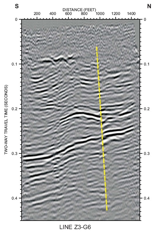
Seismic reflection results were used to confirm and better locate mapped faults impacting the corridors. Urban reflection data acquisition required special effort for success. This included data collection within active residential and other occupied areas which required resident notification, permitting, lane closures, noise mitigation, and overnight work schedules. Most of the data collection was also conducted on asphalt or concrete surfaces which led to considerations of geophone coupling and source use. Vibratory sources were selected over impact sources to counteract cultural noise omnipresent in urban environments, as well as provide improved signal response. The extra effort resulted in good data quality for most of the corridors and in some cases indicated previously unknown faults or mislocation of known faults. For example, the position of the Highland Park Fault was found to be as much as 500 feet north of its mapped position in Zone 3 (Fig. 12).
Formation Fracture Evaluation
Fracture and bedding attitudes of the rock formations were an important component for evaluating tunnel constructability. To that end, acoustic televiewer logs were employed to acquire in situ data along each corridor zone. The acoustic televiewer (ATV) provides a 360-degree image of the bore wall via use of a high-frequency rotating acoustic transducer and resolution can be as fine as 1 to 2 mm (Williams and Johnson, 2000). An example of a processed ATV log is presented on Fig. 13. Attitudes of bedding, fracturing and foliation derived from an ATV can be plotted on stereonets to identify data clustering that can provide valuable insight into local structural trends, stress history, rock quality and permeability (Fig. 14). As might be expected for a project of this size and the complex geologic environment of the site, ATV logs for the I-710 extension revealed significant heterogeneity across the different corridors evaluated. Anticipated rock conditions ranged from relatively uniform to complex. The alignment shown in Fig. 10 represents the most complex geologic environment encountered in the study. Here, tunneling considerations include unconsolidated alluvium, low strength and high strength rock, and both inactive and active faults. Use of a tunnel boring machine for excavation in this environment would require mixed-mode configuration to accommodate the geologic variability (CH2M Hill, 2009, p. 9-6). One advantage of this alignment is that it presents relatively low risk for surface settlement over most of its length. However, earth pressure balancing, watertight linings and other methods to prevent settlement and control balancing, watertight linings and other methods to prevent settlement and control high pressure groundwater inflows would need to be employed during construction
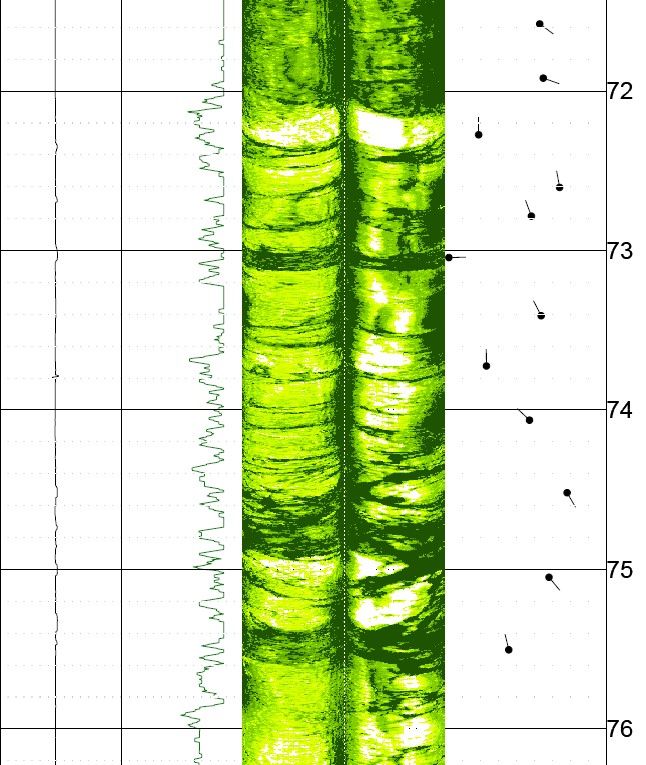
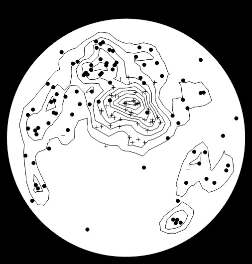
Fig. 14. Example of stereonet plot of poles-to-planes projection produced from one ATV log of the I-710 Corridor Study. Plot is projected in the upper hemisphere, which places the poles in the same compass quadrant as the dip direction. Bedding is represented by crosses, fractures by filled circles. This example shows that bedding dips predominantly north between 0 and 45 degrees, while fractures exhibit dip greater than 45 degrees and with greater scatter in direction concentrated between the north and west. A minor complementary fracture set is indicated dipping steeply to the southeast. Image courtesy Caltrans.
Program Expansion and National engagement 2005-Present
Overlapping with Caltrans’ integration into its geotechnical program was an increased presence of Caltrans’ involvement in national efforts to increase exposure of geophysical methods to a broader user base within state transportation departments. Caltrans’ Geophysics and Geology Branch contributed to many research, guidance and implementation projects sponsored by the Federal Highway Administration and the National Academies’ Cooperative Highway Research Program:
- National Cooperative Highway Research Program
- Project 20-05, Topic 36-08 (Sirles, 2006). This research synthesis helped improve understanding of the scope of use for geophysical methodologies at state transportation agencies
- Project 21-10 (Rix et al., 2019). This project revised the 1988 AASHTO Manual on Subsurface Investigations, incorporating a broader scope and role for geophysical methods in transportation geotechnical investigations.
- Project 20-05, Topic 50-01 (Rosenblad and Boeckmann, 2020). This research synthesis provided a follow-up to Topic 36-08 to gauge what progress in implementation had occurred for geophysical methodologies in the state DOTs.
- Federal Highway Administration
- EDC-5, Advanced Geotechnical Methods in Exploration (A-GaME; FHWA, 2019). Under this program, Caltrans contributes as an institutionalized user of geophysical A-GaME technologies to assist in development of incentives and implementation strategy for increasing the user base to other state DOTs.
- Strategic Highway Research Program (SHRP2)
- Product R01B (SHRP2, 2019). Unknown utilities are a leading cause of cost overruns during project construction. This project implements time-domain electromagnetic (TDEM) and ground penetrating radar (GPR) technologies to detect underground utilities and reduce uncertainty for utility locations.
- Product R06A (Gucunski et al., 2013). This project identified promising nondestructive techniques for locating and identifying deterioration in concrete bridge decks. Caltrans’ primary focus was on implementing the high speed, multichannel GPR and thermal IR components of that product.
- Product R06D (Owen, 2019). This project implements GPR, impact-echo and seismic analysis of surface waves (SASW) methods to evaluate delamination in asphalt pavements. Caltrans’ primary focus was on implementing the high speed, multichannel GPR component of that product.
- Product R06G (Wimsatt et al., 2013). This project identified nondestructive techniques for locating and identifying deterioration in concrete tunnel linings. Caltrans’ primary focus was on implementing the GPR and thermal IR components of that product.
The SHRP2 projects represent an expansion and spinoff of the Geophysics and Geology Branch mission to include cutting-edge nondestructive evaluation (NDE) for transportation infrastructure. This seemingly contradictory evolution is actually a natural extension of similar technologies from the investigation of deep foundations to the study of very shallow structures. It allows Caltrans the ability to most efficiently distribute those resources to the people with the most experience and expertise, and provides the best return on the investment in those technologies.
Conclusion
Ultimately, the goal of integrating geophysical technologies into geotechnical investigations is to maximize return on investment so that, even though investigation costs are slightly increased at the design phase, those additional early costs are more than offset by reducing cost overruns in the construction phase related to unforeseen site conditions. Caltrans, as an institutionalized user of many of the A-GaME technologies, successfully employs a multidisciplinary approach to subsurface characterization for the design of high value structures. Caltrans uses geophysical methods both to guide the exploration drilling program and to expand subsurface information beyond the drill hole. We also use borehole geophysical methods to maximize the return on drilling investment by increasing the amount of data that can be obtained from test borings. In that manner, we complement the traditional destructive investigation methods and laboratory test data to help provide a more comprehensive picture of site conditions.
Future implementation of geophysical technologies sees Caltrans continuing to provide A-GaME services for deep foundations and expanding service to include related NDE investigations for pavement and structural elements as well as subsurface utility locating. With those additional services, we provide added value for supporting our infrastructure maintenance and structure design functions. As an institutionalized user of geophysical methods, Caltrans’ geophysical program and experience provides vetted guidance and proven examples to aid other organizations in advancing the state of practice for geotechnical site characterization.
REFERENCES
Allen, J.M., 2000, Addendum archaeological survey report – maritime archaeology, report prepared for California Dept. Transportation District 4, Caltrans Contract 04A0148, Task Order 175.10.15, pp.
Boeckmann, A.Z. and Loehr, J.E., 2016, Influence of Geotechnical Investigation and Subsurface Conditions on Claims, Change Orders, and Overruns, NCHRP Synthesis 484, National Academies Press, 76 p.
Caltrans, 2012, Methodology for developing design response spectrum for use in seismic design recommendations, http://dap3.dot.ca.gov/ARS_Online/Tech_Docs/Methodology%20for%20 Develop ing%20DRS_12-5-12.pdf.
Caltrans, 2017, Geotechnical Investigations, Caltrans Geotechnical Manual, https://dot.ca.gov/-/media/dot-media/programs/engineering/documents/geotechnical-services/geotechnical-investigations-july2017r1-a11y.pdf.
Caltrans, 2018, Geophysics and Geology Branch fact sheet, California Dept. Transportation, 2 p.
CH2M Hill, 2009, SR-710 tunnel technical study, Los Angeles County, California, report prepared for California Dept Transportation, pp.
FHWA (Federal Highway Administration), 2018, Advanced geotechnical methods in Exploration (A-GaME), Every Day Counts-Onramp to Innovation fact sheet, https://www.fhwa.dot.gov/innovation/ everydaycounts/edc_5/docs/advanced-geotech-factsheet.pdf.
FHWA, 2019, Every Day Counts: Onramp to Innovation, EDC-5 Summit summary and baseline, https://www.fhwa.dot.gov/innovation/everydaycounts/reports/edc5_baseline/.
Fugro-Earth Mechanics, 1998, SFOBB east span, seismic safety project, 30% type selection, report prepared for California Dept. Transportation, p 10-11.
Fugro-Earth Mechanics, 2001a, Final marine geotechnical site characterization, San Francisco-Oakland Bay Bridge east span seismic safety project, volume 1-main text, report prepared for California Dept. Transportation, pp.
Fugro-Earth Mechanics, 2001b, Final marine geophysical survey, San Francisco-Oakland Bay Bridge east span seismic safety project, volume 1-main text & appendices, report prepared for California Dept. Transportation, pp.
Fugro-Earth Mechanics, 2001c, Axial pile design and driveability, main span-east pier & skyway structures, San Francisco-Oakland Bay Bridge east span seismic safety project, report prepared for California Dept. Transportation, pp.
Gucunski, N., Imani, A., Romero, F., Nazarian, S., Yuan, D., Wiggenhauser, H., Shokouhi, P., Taffe, A. and Kutubres, D., 2013, Nondestructive Testing to Identify Concrete Bridge Deck Deterioration, SHRP2 Report S2-R06A-RR-1, National Academies Press, Washington, D.C., http://www.trb.org/ Main/Blurbs/167278.aspx.
Owen, W.P., 2000, Selling geophysics: some observations on creating and marketing a geophysics program in state government, Proceedings of the 1st International Conference on the Application of Geophysical Methodologies & NDT to Transportation Facilities and Infrastructure (Geophysics 2000), St. Louis, MO, December 11-15, 2000, Paper 1-11, 10 p.
Owen, W.P., 2019, SHRP2 product implementation close out report – Advanced Methods to Detect Pavement Delamination, California Dept. Transportation, 42 p.
Rix, G.J., Wainaina, N., Ebrahimi, A., Bachus, R.C., Limas, M., Sancio, R., Fait, B., and Mayne, P.W., 2019, Manual on Subsurface Investigations, NCHRP Web-Only Document 258, National Academies Press, Washington, D.C., http://www.trb.org/Main/Blurbs/178722.aspx.
Rosenblad, B.L. and Boeckmann, A., 2020, Advancements in Use of Geophysical Methods for Transportation Projects, NCHRP Synthesis 20-05/Topic 50-01, National Academies Press, Washington, D.C., https://rip.trb.org/ view/1512301.
SHRP2 (Strategic Highway Research Program), 2019, SHRP2 utilities solutions peer exchange and retrospective workshop report, http://shrp2.transportation.org/documents/SHRP2_Utilities_Focus_ Area_Final_Report_8_26_19.pdf
Sirles, P., 2006, Use of Geophysics for Transportation Projects, NCHRP Synthesis 357, National Academies Press, Washington, D.C., http://onlinepubs.trb.org/onlinepubs/nchrp/ nchrp_syn_357.pdf.
Williams, J.H., and Johnson, C.D., 2000, Borehole-wall imaging with acoustic and optical televiewers for fractured-bedrock aquifer investigations, in Seventh International Symposium on Borehole Geophysics for Minerals, Geotechnical, and Groundwater Applications, October 24-24, 2000, Proceedings: Minerals and Geotechnical Logging Society, Houston, p.43-53, https://water.usgs.gov/ogw/ /bgas/publications/mgls2000/mgls2000.pdf.
Wimsatt., A., White, J., Leung, C., Scullion, T., Hurlebaus, S., Zollinger, D., Grasley, Z., Nazarian, S., Azari, H., Yuan, D., Parisa, S., Saarenketo, T. and Tonon, F., 2013, Mapping Voids, Debonding, Delaminations, Moisture, and Other Defects Behind or Within Tunnel Linings, SHRP2 Report S2-R06G-RR-1, National Academies Press, Washington, D.C., http://www.trb.org/Main/ Blurbs/168768.aspx.
Author`s Bio
William Owen
Bill Owen is a Professional Geophysicist and chief of the Geophysics and Geology Branch for the California Department of Transportation in Sacramento. He has 27 years of experience managing and conducting engineering geophysical investigations for highway infrastructure throughout the state. He has also participated in national research projects and federal outreach efforts demonstrating the efficacy of geophysical methods for engineering problems.

William Dalrymple
William Dalrymple is a Professional Geophysicist with the Geophysics and Geology Branch at the California Department of Transportation. He has 16 years’ experience, both private and public, conducting geophysical projects for highways, dams, mine sites, nuclear and chemical plants, and environmental sites worldwide. His current focus is on performing seismic, electrical, electromagnetic, and GPR investigations for transportation projects throughout California.
Benjamin Rivers
Ben is Senior Geotechnical Engineer with the Federal Highway Administration (FHWA). He has 27 years of experience in the geotechnical field and has worked in both the private and public sectors. His current areas of focus with FHWA include subsurface investigation and geotechnical site characterization, earthwork, geohazards, soil and rock slopes, and drilled shaft construction. He also leads the current Every Day Counts (EDC) effort on Advanced Geotechnical Methods in Exploration (The A-GaME).
