Robert L. Gordon
Leduar Ramayo Cortes
Abstract
The last 20 years have seen significant improvements in geophysical technology. Several geophysical systems have been developed to collect deep, accurate, rock property information. This information includes resistivity and chargeability measurements. While geophysical surveys are usually associated with the exploration stage, collecting deep information at the mine planning stage provides key insights about the subsurface that contribute to more effective mine plans, reducing associated long-term risks to mine operations. The geophysical systems used have features that allow them to produce accurate chargeability and resistivity images to depths of up to 800 and 1500 metres respectively. These images are key for exploration but can also be directly related to critical features of the subsurface that can impact mine design, such as the location of mineralization, clay layers, faults, shears and aquifers. These modern systems can collect and produce results quite quickly and therefore will not delay the feasibility stage of new mines.Deep, large-scale, images can be used to assist condemnation drilling, and map geology and other structural information which may impact the overall plan. Collected in large volumes, these parameters can also provide a roadmap for future exploration activities following commissioning. In some cases the discovery of additional satellite deposits at the mine development stage can help avoid unfortunate and costly situations such as locating tailings ponds and other infrastructure directly over ore which exists proximal to the original discovery but was undiscovered at the time of planning.The paper explains how deep penetrating geophysical surveys provide key information that can assist the planning stage. Several case studies highlight practical applications.Keywordsbrownfield, minesite, tailings planning, exploration, geophysics.
Technology
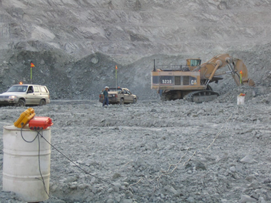
In 1994, John Kingman introduced the concept of digital signal processing to mineral exploration and this led to a paradigm shift in geophysical instrumentation.(Kingman 1984) This work lead to the advent of distributed acquisition systems for data collection. The first systems were introduced in (1998), when Sheard et al. unveiled a distributed acquisition system (DAS) with time-series acquisition, current-monitoring, MT capability, and telluric cancellation. In 2000, the first commercial surveys were carried out in greenfield environment (Gordon 2006) Now, detailed and deep imaging is used routinely in greenfield exploration.The technology has been further developed to a point where it can now be used in brownfield exploration. Minesites typically have high ambient noise, and very few imaging technologies work effectively there. Distributed networks of sensors collect full waveform, high resolution data, and advanced digital signal processing methods are able to capture small signals through the mine-generated noise, providing valuable geological models (Sharpe 2018).The use of these technologies for exploration activities near older mines where new orebodies might extend the life of mine has been successfully demonstrated (Figure 1).The application of MT technology, used routinely in academia for very deep (25 km) regional studies, for very detailed deep (2000m) mineral exploration surveys has been combined with deep penetrating DCIP surveys to produce deep and accurate multi-parameter data. Resistivity and chargeability models are now routinely provided to roughly 800 m depth. MT resistivity surveys further extend this down to 1500 m depth (Figure 2). More recently, full 3D surveys have provided even greater imaging capability in geologically complex environments.
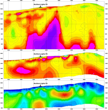
In several situations, the data collected from these exploratory surveys has added valuable information for mine planning.
Implications at the Minesite for Mine Planning
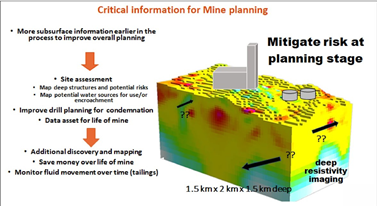
Often in mine development, after the initial discovery many activities occur that no longer require or typically use geophysics. Mine planning and development from pre-feasibility through feasibility involve various levels of study and information gathering. These traditionally involve environmental studies, design work, geotechnical and hydrogeological work. In some cases shallow applications of geophysics are used as baseline work for some design criteria, and some hydrogeological studies can be conducted, but rarely do these surveys provide information to depths greater than 50 metres. Recently, the industry has acknowledged that factors that contribute to increased minesite include a lack of thorough planning information at the time of development. Deep earth imaging can provide a number of benefits at the feasibility and planning stages and may contribute to risk mitigation on several fronts (Figure 3).
Condemnation
One of the most significant issues at the planning stage that helps mitigate risk is effective ground condemnation. Up until very recently, drilling has been the principal means for ground condemnation. Condemnation issues may relate to competency of rock in an area where a shaft is required or checking to ensure additional undiscovered ore is not under a proposed mill location. Testing for aquifers is another aspect of condemnation drilling. Today, with the advent of improved deep imaging, condemnation drilling can be more effective if planned in conjunction with results from these deep images. Several key factors should be considered when evaluating the effectiveness of proper ground condemnation. Are the sites selected for tailings and infrastructure such as office facilities, roads and the mill located on top of ore which may need to be mined in the future?Is the subsurface competent underneath and surrounding a planned tailings location? Are there any deep-seated structural features that may be unstable should there be an earthquake or that may provide deep permeability that could provide conduits for water and or effluent movement?Significant issues will arise in the future if the location of tailings or other infrastructure is found to overlie a nearby satellite ore body. Figure 4 shows the location of several near mine orebodies at the Century Zinc deposit in Australia, that could have been jeopardized had infrastructure been placed in those locations.In fact, the East Fault Block is a small deposit located 35m below the surface of the run-of-mine stockpile area at the
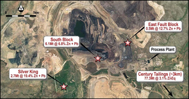
mine site and extends to a depth of 112m. Early location of such satellite bodies can a), provide additional reserves and value to the discovery and b), assist with planning and design of infrastructure.
Data asset for future exploration
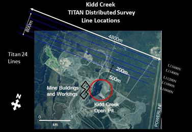
The information collected for condemnation surveys can provide additional useful information as the mine starts up. It can also address a critical issue that occurs at the hand-off to mine operations, when the mine takes on a complete new life of its own. The hand-off from discovery has sometimes been termed the “donut of information”, referring to a very real situation where critical and missing information goes undetected or undiscovered, and is not shared across the many different multi-disciplinary groups that are now involved at a producing mine. On the exploration side this might mean valuable exploration information that was collected just before the discovery has become lost, and future explorers at the mine lose its key value.Having a 3D database of subsurface information can be useful for future planning and also provide guidance for future exploration activities near the mine. The following example demonstrates the results of a near mine survey that was executed near the end of life at the Kidd Creek mine in Northern Ontario. The study demonstrates the importance and the potential cost savings, had the technology been applied at an early stage of mine planning and development. A multi-parameter deep imaging survey was deployed for near mine exploration. The survey occurred over an area of 5 km by 1 km only 500m from the pit at the top of the mine (Figure 5).The blind test survey was successful at identifying 100 % of the known targets previously drilled within the top 800 metres. The survey indicated a significant region as being barren (Figure 6), highlighting the potential value of these surveys in avoiding unnecessary drilling costs.

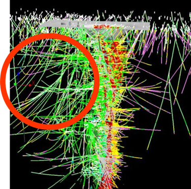
During the life of mine, without the benefit of the survey, extensive near mine exploration had been carried out. Hundreds of barren drill holes were drilled over 15 years at an estimated cost of over 15 million dollars. Had the survey been done up front, the same ground would have been identified as barren, but in just a few weeks and for only about $300,000.00 (Figure 7).
Brownfield exploration
Not long after a mine is commissioned, mine site exploration starts to play a role in the overall mix of activities of the mine. In some cases this means at the mine or near the mine (<3km). This is referred to as brownfield exploration.Life of mine realities dictate an early desire to find more ore in close proximity to the mine. As infrastructure is operational and in place for processing and refining, huge cost benefits exist by adding to reserves close to the mine. However, traditionally geophysical techniques are hampered by cultural and electrical noise which occur near the mine. The features of distributed systems make them ideal for mine site applications. While noise can impede acquisition, these systems have demonstrated that reliable deep information can still be collected. It is arguable that the time for additional
deep looking surveys is right at the beginning of a mine’s life, i.e. before infrastructure has been placed.
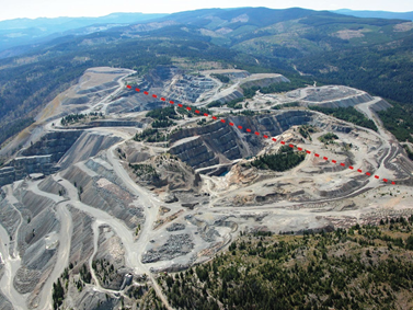
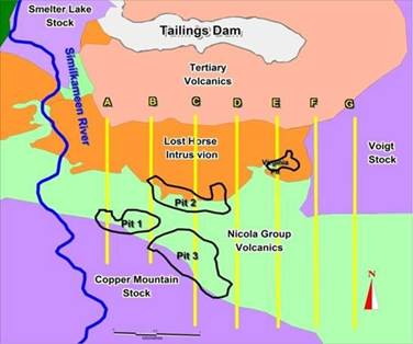
At Copper Mountain (Figure 8) in south central B.C., a deep survey was employed to test for near mine zones. Several long lines were set up and surveyed for deep DC resistivity and IP. The survey involved 7 lines of data collection (Figure 9).
The results of the survey were spectacular and highlighted several unique applications of the technology; most significant was the discovery of new ore below the pit which contributed to the extension of mine life (Figure 10).
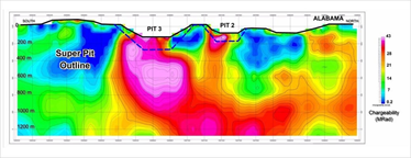

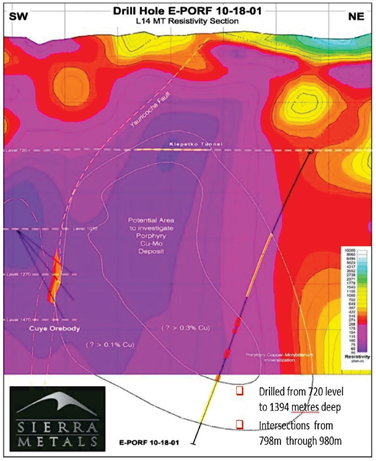
In addition, the survey data contributed to several other important aspects at the site. The use of the images help speed up a portion of the environmental permitting process, by demonstrating consistency of the underlying sub-surface in the area of a tailings plan. Plans for extensive acid base drilling could also be adjusted based on the correlation of geology and the images. This contributed to less drilling in an area planned for tailings. Finally, the overall mine plan was changed significantly to address the new discovery (Figure 11).Another recent example of in mine exploration is from the Yauricocha Mine in Peru. Until very recently mineralization at the Yauricocha Mine has been represented by variably oxidized portions of a multiple-phase polymetallic system with at least two stages of mineralization, demonstrated by sulfide veins cutting brecciated polymetallic sulfide mineralized bodies. A deep mine site survey was designed with 23 2.4 km long lines, spaced 200 m apart. Sierra Metals confirmed the discovery of a new style of mineralization based on testing of the deep geophysical anomalies, in the quartz monzonite intrusive. Drilling from an underground adit at the 700 m level of a new style of mineralization (porphyry) at over 1,300 m was based on deep electrical earth imaging provided by MT data (Figure 12).
Tailings Dams
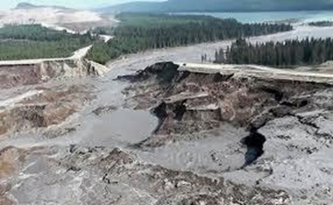
At the Mt. Polley mine a significant tailings failure occurred in part due to an undetected clay layer below the site of the tailings. Had deeper imaging been deployed, the detection of such features at the mine planning stage could have resulted in a different layout or location for the tailings, or other appropriate mitigation factors (Figure 13).
Earthquake risk
Although earthquake risk is often very small, understanding the potential location of deep-seated pre-existing fault systems is another area where deep resistivity surveys can provide information about potential risks at the planning stage. Fault systems typically host water and moisture and can be detected to great depths by MT resistivity surveys.
Further advances in geophysical technology: 3D electrical imaging systems
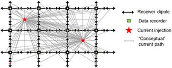
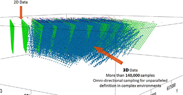
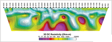
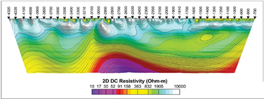
Following the lead of the oil industry, 3D technology was developed to address the limitations of imaging 3D geology with 2D methods. 3D surveys allow omnidirectional measurement of the ground for both DCIP and MT. The omnidirectional coverage eliminates the inherent directional bias of 2D surveys. Deployment of independent receivers can be quite flexible and does not require a set grid or lines. For every current injection, all receivers are active and measuring simultaneously, resulting in better imaging of the subsurface (Figure 14).Following the complete acquisition process of multiple current injections, the result is greater volumes of data that are most representative of the 3D geology and structure (Figure 15).The increase in data volume coupled with omnidirectional sampling has been the basis for highly data constrained 3D models. To achieve this required significant increases in computing power that has only occurred in the last 10 years. In Figure 16 we see significantly more detail extracted from a full 3D survey. Typical deployment for 3D surveys is at a scale of 2 km x 2 km and greater, with either all receivers deployed at once or deployed in roll along set-ups. Although these surveys can involve flexible deployment, working in active mines presents logistical constraints and data can still be hampered by culture.
Coordinated planning is required for active mine site programs but surveys are easily deployed for pre-mine and near mine applications.
Future applications: 4D Monitoring Hydrology and Contamination
The need to prevent pollution of the groundwater below and adjacent to tailings disposal sites is an important design consideration. In most situations ongoing risks to the environment are waterborne contamination arising from seepage through the deposited tailings, or contaminated runoff polluting downstream watercourses. Liners can deteriorate over time and effluent material can seep deep into the water table. Many older designs were started at a time when there was less concern for or appreciation of the need to protect the environment.Groundwater pollution is typically detected by monitoring the quality of groundwater samples obtained from observation wells located downstream of the impoundment. However, contamination may not be occurring at the location of the observation well sites. Detecting contaminants between well sites is warranted.The conductive nature of typical tailings makes them an ideal candidate for remote monitoring with the resistivity method. By monitoring the changing resistivity model over time, changes in the conductivity signature over time can raise red flags for early follow-up.
Conclusions
Multi-parameter geophysical surveys provide key rock property information about the subsurface. With the ability to measure small signals in a background of noise, accurate deep imaging is available to aid mine planning and help address life of mine issues. Significant cost savings can be made by imaging in and around mine sites prior to blanket drilling. Deep MT resistivity imaging, especially when coupled with IP, provides a window into the unknown geological environment at the mine site. Deployment of these technologies at an early stage immediately after discovery can help provide risk mitigation and enhance future exploration initiatives at the mine. As evidenced by many actual examples, improved condemnation planning, enhanced targeting and ultimately more efficient use of drilling budgets while working around the mine are all facilitated by an early, well designed geophysical survey.
Acknowledgement
The author wishes to thank Peter Holbek from Copper Mountain for valuable insight on the use of geophysics at the mine site as well as Sierra Metals and Kidd Creek Mines for use of data examples.
References
Kingman, J., 1994, Digital signal processing approaches to interpreting induced polarization data: John S. Sumner memorial international workshop on IP in mining and the Environment, Tucson AZGordon, R., 2006, New technology approach needed for mining industry. First Break, Vol 24, July 2006.Sharpe, R. [1], Gordon, R. [1], Zhurba, A. [1], Data, E. [1], 2018. A decade of technological advances in distributed IP & Resistivity. Why it was needed. What was achieved.New Century Resources website.2020. www.newcenturyresources.com
Author Bios

Rob Gordon P. Eng., MBA., HFGC
Graduated Queens University, Kingston 1985 Geological Engineer, (Engineering Geo- physics)
Western University MBA 2002
Rob has worked in the exploration industry since 1981. He has experience in most sides of the exploration business and has been involved in exploration for most commodities. Rob’s background has been based on both geological and geophysical approaches to exploration. Positions have included geological regional prospecting and geochemical surveys, for Anaconda based in BC, Mine site Exploration at Lupin in the NWT for Echo Bay Mines. Consulting Geophysicist for Covello Bryan Consulting, Project Geophysicist with Terraquest airborne, Operations manager for Dighem, Manager Geophysics, at Quantec Canada. Subsequently Rob lead Caracle Creek, an international Geological consulting house where he was providing both geological and geophysical solutions to the industry. Rob was privileged to be Senior project Geophysicist on all major airborne projects flown by Dighem in the early 90’s. These included all State of Alaska Regional Helicopter EM Airborne programs, a major UNDP development program in southern Ethiopia. In addition, he coordinated and provided target information during the diamond rush in the NWT including BHP’s major exploration and discovery work of the Ekati Mine and the Diamond Field’s Nickel discovery at Voisey’s Bay. Rob provides technical solutions for the mining & exploration industry and leads the team for business development at Quantec.

Leduar Ramayo Cortes
Quantec Geoscience,
146 Sparks Ave, Toronto, Canada
Academic History:• University of Moa, Holguin, Cuba.• Engineer (Geology Option). 1989-1994• Master (Geochemistry Option) 1994 – 1996• La Plata National University, Buenos Aires, Argentina• PhD in Natural Sciences (Geology Option). 1998-2001Leduar has 20 years of experience in exploration in the Mining Industry, working in a wide variety of geologic settings and exploration environments. Currently, Leduar develops exploration programs, from area selection to target definition.He has a broad range of experience and involvement in geophysical surveying, QC and interpretation of geophysics. He has technical knowledge of all aspects of ground geophysical survey techniques including time-domain and frequency-domain EM, gravity, magnetics, radiometrics, and the interpretation of such surveysAs the Senior Geoscientist and Business Development for Quantec Geoscience, he is part of a multidiscipline team with a strong background in geoscience. He helps clients achieve their exploration objectives. He has worked in most countries of South America including Argentina, Chile, Brazil, Bolivia, Ecuador, Paraguay, Colombia, Peru, Cuba, Dominican Republic, and Mexico.

